Star – Delta Motor Control Using Schneider Zelio Logic PLC Smart Relay
How to Wire Automatic Star – Delta Control Circuit For Motors Using Schneider Zelio Logic PLC Smart Relay?
In industrial automation and applications, three-phase induction motors are commonly used due to their efficiency and high starting torque. However, during startup, these motors draw a high inrush current that can damage the motor and cause instability in the power grid. To address this issue, Star-Delta Motor Control is used to reduce the inrush current during startup. In this article, we will discuss how to implement a Star-Delta Motor Control Circuit using Schneider Zelio Logic PLC Smart Relay.
What is Star-Delta Motor Control?
Star-Delta Motor Control is a method of reducing the inrush current of a three-phase induction motor during startup. The circuit involves connecting the motor windings in a star configuration during startup, and then switching to a delta configuration once the motor has reached full speed. By doing so, the inrush current is reduced, and the motor is protected from damage.
What is Schneider Zelio Logic PLC Smart Relay?
Schneider Zelio Logic PLC Smart Relay is a compact and versatile controller that can be easily programmed for a variety of applications. It is a powerful device that combines the functions of a programmable logic controller (PLC) and a smart relay. The Zelio Logic PLC Smart Relay is designed to simplify the implementation of control systems, making it an ideal solution for industrial automation applications.
Related Posts:
- Star – Delta Starter Motor Control Circuit Using S7-1200 PLC
- Automatic Star – Delta Starter Motor Control Circuit Using LOGO! V8 PLC
Hardware Requirements
To implement the Star-Delta Motor Control Circuit using Schneider Zelio Logic PLC Smart Relay, the following hardware components are required:
- Schneider Zelio Logic PLC Smart Relay
- Three-phase induction motor
- 1-Phase & 3-Phase power supply
- Three-phase contactors
- Single phase & three-phase circuit breakers
- 4 Nos of Pilot Light Panel Indicator bulbs
- 2 Nos of NC Push Buttons Switches
- Thermal Overload Relay
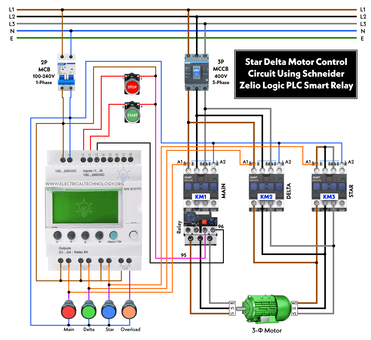
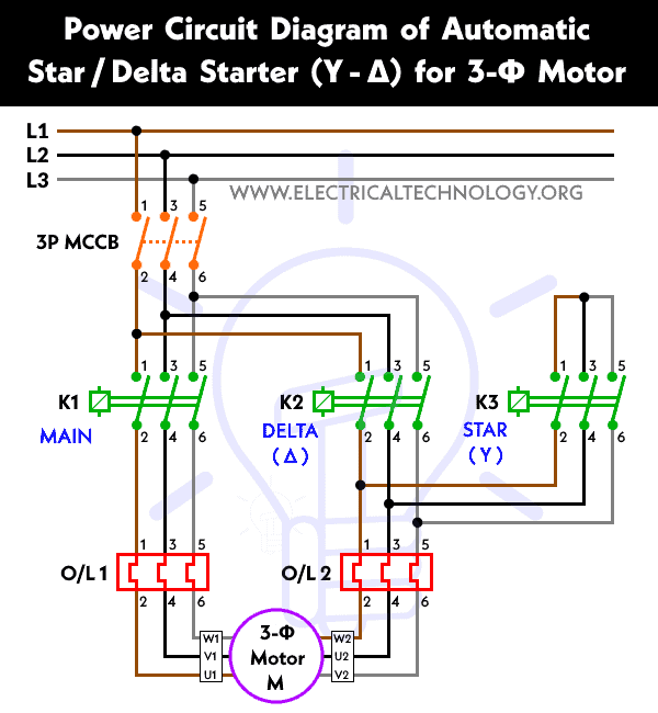
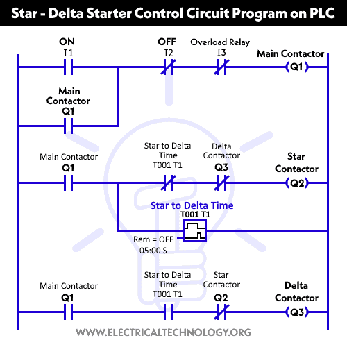
Wiring, Power & Ladder Control Diagrams
Wiring Diagram
Click image to enlarge
Power Diagram
Ladder Control Diagram
Related Posts:
- Star – Delta Motor Control Circuit Using Omron PLC ZEN Programming Relay
- Star – Delta Motor Control Circuit Using Delta – DVP 14SS2 Series PLC
Programming Steps
Step 1: Create a New Project
Create a new project in Schneider Electric’s Zelio Soft 2 software and select the appropriate Zelio Logic PLC Smart Relay model. Once the project is created, create a new ladder diagram program.
Step 2: Create the Control Section
The control section is responsible for controlling the switching between the star and delta configurations. In this section, a timer is used to delay the switching from the star to the delta configuration. This delay allows the motor to reach full speed before the circuit switches to the delta configuration. To create the control section, follow these steps:
- Create a timer function block.
- Set the timer value to the required delay time.
- Connect the output of the timer to a relay function block.
- Set the relay function block to activate the delta contactor.
Step 3: Create the Star Section
The star section is responsible for connecting the motor in a star configuration. In this section, three relay function blocks are used to connect the motor to the power supply. Each relay function block is responsible for connecting one phase of the motor to the supply. A fourth relay function block is used to connect the neutral wire to the supply. To create the star section, follow these steps:
- Create three relay function blocks.
- Connect the outputs of the relay function blocks to the contactors.
- Set the relay function blocks to activate the contactors.
- Create a fourth relay function block.
- Connect the output of the fourth relay function block to the neutral contactor.
- Set the fourth relay function block to activate the neutral contactor.
Step 4: Create the Delta Section
The delta section is responsible for connecting the motor in a delta configuration. In this section, three relay function blocks are used to connect the motor to the power supply. Each relay function block is responsible for connecting two phases of the motor to the supply. To create the delta section, follow these steps:
- Create three relay function blocks.
- Connect the outputs of the relay function blocks to the contactors.
- Set the relay function blocks to activate the contactors.
Step 5: Create the Main Program
The main program is responsible for calling the control section, the star section, and the delta section. It also sets the initial state of the relays to ensure that the motor starts in the star configuration. To create the main program, follow these steps:
- Create a main program.
- Call the control section.
- Call the star section.
- Set the initial state of the star section relay
Step 6: Create the Input Devices
The input devices are responsible for detecting the status of the motor and the start/stop commands. In this circuit, two input devices are used: a motor thermistor and a start/stop button. The motor thermistor is used to detect the motor temperature and protect it against overheating. The start/stop button is used to start and stop the motor. To create the input devices, follow these steps:
- Create an analog input function block for the motor thermistor.
- Connect the analog input function block to the thermistor.
- Create a digital input function block for the start/stop button.
- Connect the digital input function block to the button.
Step 7: Create the Output Devices
The output devices are responsible for controlling the contactors and the motor. In this circuit, four output devices are used: three contactor function blocks and one motor function block. The contactor function blocks are used to control the three-phase contactors, while the motor function block is used to control the motor. To create the output devices, follow these steps:
- Create three contactor function blocks.
- Connect the outputs of the contactor function blocks to the contactors.
- Set the contactor function blocks to activate the contactors.
- Create a motor function block.
- Connect the output of the motor function block to the motor.
- Set the motor function block to activate the motor.
Step 8: Create the Logic Connections
Once the input and output devices are created, the logic connections need to be established to control the Star-Delta Motor Control Circuit. To create the logic connections, follow these steps:
Connect the output of the motor thermistor analog input function block to a comparator function block.
Set the comparator function block to activate the motor function block when the motor temperature is below the threshold.
- Connect the output of the start/stop button digital input function block to a memory function block.
- Connect the output of the memory function block to the control section.
- Set the memory function block to remember the last state of the start/stop button.
- Connect the output of the control section relay function block to the contactor function blocks.
- Set the contactor function blocks to activate the contactors based on the switching from star to delta configuration.
Step 9: Download and Test the Program
Once the logic connections are established, download the program to the Schneider Zelio Logic PLC Smart Relay and test it with the motor. Verify that the motor starts and stops correctly and that the switching between star and delta configurations is working as expected.
Related Power & Control Wiring Diagrams for Motors
- Star/Delta Starter Using a Programmable Logic Controller (PLC) – Ladder & Wiring Diagrams.
- Automatic Star-Delta Starter using Timer – Power, Control & Wiring Diagrams
- STAR/DELTA Starter Without Timer – Power, Control & Wiring Diagrams
- Reverse/Forward Circuit for Motors using Start Delta & Timer – Power & Control Diagrams
- Reverse / Forward Circuit for 3-Phase Motors – Power & Control Diagrams
- Reverse Forward Motor Control Circuit Using PLC – ZEN Programming Relay
- Reverse Forward Motor Control Circuit Using Mitsubishi FX Series PLC
- Automatic Reverse Forward Motor Control Using S7-1200 PLC
- Automatic Reverse – Forward Motor Control Circuit Using Omron CP2E PLC
- Automatic Reverse Forward Motor Control Circuit Using Delta – DVP-14SS PLC
- Automatic Sequential Operations of Motors – Power, Control, PLC & Wiring Circuits
- Three Phase Slip Ring Rotor Starter – Control & Power Diagrams
- Starting & Stopping of 3-Phase Motor from More than One Place – Power & Control Diagrams
- ON / OFF Three-Phase Motor Circuit – Schematic Power, Control & Wiring Diagrams
- Controlling of 3-Phase Motor from More than Two Places – Power & Control Diagrams
- Multispeed (2 Speeds, 2 Directions) 3-Phase Motor Power & Control Diagrams
- Multispeed (2 Speeds, 1 Direction) 3-Phase Motor Power & Control Diagrams
- Multispeed (3 Speeds, 1 Direction) 3-Phase Motor – Power & Control Diagrams


