Ring Counter & Johnson Counter – Construction & Operation
Construction & Working of Ring Counter & Johnson Counter
What is Ring Counter & Johnson Counter?
In our previous post, we have discussed different types of electronic counters in details, to the ring counter, a type of counter in which the output of the last flip-flop is connected as an input to the first flip-flop is known as a Ring counter. The input is shifted between the flip-flops in a ring shape which is why it is known as a Ring counter.
A Ring counter is a synchronous counter. the synchronous counter has a common clock signal that triggers all the Flip-flops at the same time. Ring counter consists of D-flip flops connected in cascade setup with the output of last Flip-flop connected to the input of first Flip-flop. Each flip-flop constitutes a stage.
This counter is developed by modifying a shift register. The true output of the last flip-flop is fed back directly to the data input of the first flip-flop, thus generating a sequence of pulses. For example, for a D Flip-Flop shift register, the Q output of the last flip-flop is connected to the D input of the first flip-flop. These counters are used in digital system to generate control pulses. Johnson counter is a reverse of Ring Counter. In other words, feedback from the last flip-flop is fed inversely to the data input of the first flip-flop. For example, for a D Flip-Flop shift register, the ~Q output of the last flip-flop is fed to the D input of the first flip-flop. These can be used as Divide by n counters as well.
Difference between Ring Counter & Johnson Counter?
Ring Counter:
Johnson Counter
Types of Ring Counters
There are two types of the Ring counter.
- A Typical Ring Counter
- Johnson counter
Typical Ring Counter
A typical 4-bit ring counter is made of D-flip flops or JK-flip flop connected in cascade with the non-complemented output of the last stage connected as an input to the first stage. Ring counter has Mod = n ‘n’ is the number of bits. It means 4-bit ring counter has 4 states.
Ring Counter Truth Table
Consider QA, QB, QC, QD as the 4 bits of the ring counter. The truth table for 4-bit ring counter is given below.
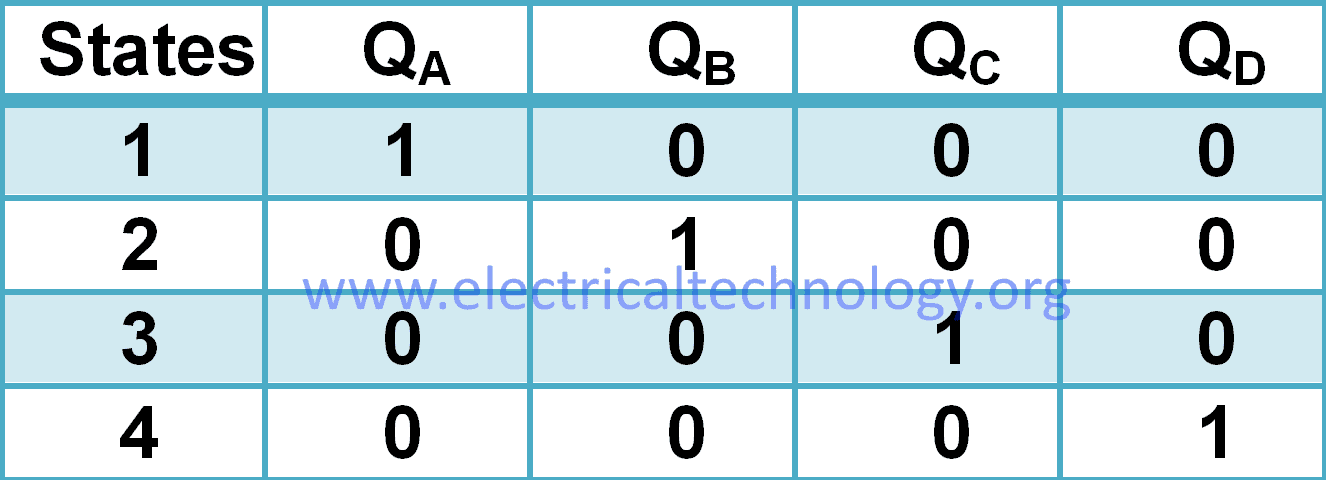
In ring counter, logic ‘1’ flows through all stages of the counter. In each state, it flows one bit to the right. When it reaches stage 4, it circulates back to stage1 of the counter.
Working of Ring Counter
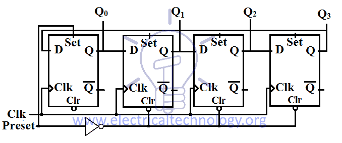
Ring counter’s state needs to be set before the operation. Since ring counter circulates 1 through all stages, and there are no external inputs except the clock signal. So we need to set its state to initial state 1000 manually. We need to set the first stage flip-flop and clear the rest of the stages to obtain the state 1000.The preset input pin is designed to do this function. The schematic of ring counter is given below:
First, we need to set the initial state 1000 through preset input.
Whenever the first clock edge hits the counter the outputs of each stage shifts to the next succeeding stage. And the output of the last will shift to the first stage making the state 0100.
Upon next clock cycle, each stage will update its state according to its input. So the ‘1’ will be shifted to the third stage making the state 0010. Upon another clock cycle, the ‘1’ will reach the last stage making the 0001.
Now upon next clock cycle, ‘1’ from the last stage (flip-flop) will shift back to the first stage making the initial state 1000. And it starts again from the first state repeating itself considering the clock signal is provided. This is how the data inside the ring counter circulates in the ring.
Ring counter divides the frequency of the clock signal by ‘n’. n is the bit size of the ring counter. So ring counter can be used as a frequency divider.
Advantages / Disadvantages of Ring Counter
Advantages
- It doesn’t need a decoder (i.e. It is a self decoding circuit)
- It can be can be implemented using JK and D flip-flops.
Disadvantages
- In ring counter, only 4 of the 15 states are being utilized.
What is Johnson Counter
“Johnson counter” or “twisted ring counter” is a type of synchronous ring counter in which the complemented output of the flip-flop is connected with the input of the first flip-flop. Johnson counter can be made with D-flip flops or JK-flip flops in cascade setup.
The Mod of Johnson counter is ‘2n’, n is the bit size of the counter. Mod is the maximum number of states a counter can obtain.
Johnson Counter Truth Table
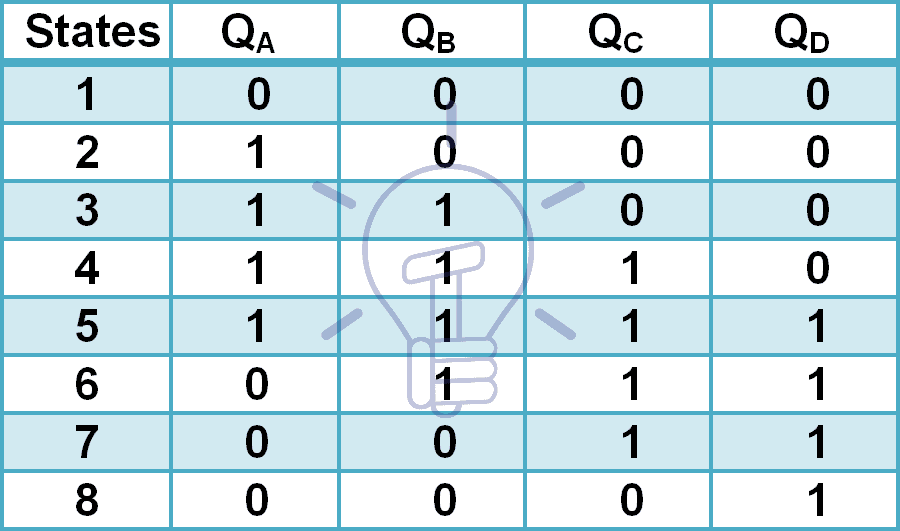
Consider a 4-bit Johnson counter with QA, QB, QC, QD as the output of 4 stages of the counter. The truth table of the 4-bit Johnson counter is given below;
Johnson Counter Schematic Design
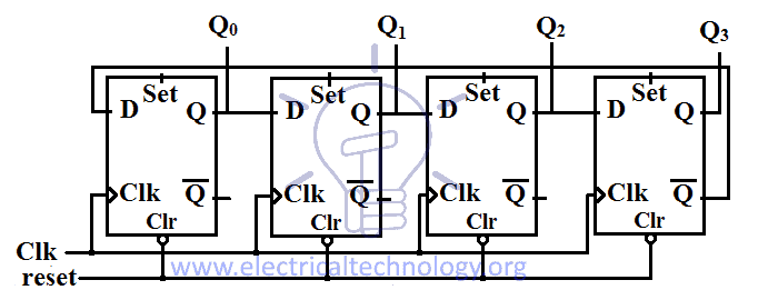
The schematic of 4-bit Johnson counter consists of 4 D-flip flops or 4 JK-flip flops. These flip-flops are connected with each other in cascade setup. The output of each flip-flop is connected with the input of the succeeding flip-flop. The complemented output of the last flip-flop is connected with the input of the first flip-flop. The Same clock input is connected with all flip-flops. There is clear input for resetting the state to default 0000. Johnson counter’s schematic design is given below.
Working of Johnson Counter
The default state of Johnson counter is 0000 thus before starting the clock input we need to clear the counter using clear input.
Whenever a clock edge hits the counter the output of each flip-flop will transfer to the next stage (flip-flop) but the inverted output of the last flip-flop will shift to the first stage making the state 1000.
Upon next clock cycle, another ‘1’ will stack in from the left side as the inverted output of the last stage will be shifted to the first stage.
On next clock cycle, another ‘1’ will add in from left until the state becomes 1111.
Now that the last flip-flop’s output is ‘1’, the next clock cycle will shift the invert of the last flip-flop which is ‘0’ into the first flip-flop. It will result in stacking ‘0’ from the left side. This stacking of the first 0 will make the state 1111 into 0111.
The next coming clock cycles will stack in 0’s from the left making the states 0011, 0001 & 0000 with each clock cycle. Eventually, it reaches its default state and it starts from the beginning again.
- You may also read: Ripple Carry And Carry Look Ahead Adder
Advantages / Disadvantages of Johnson Counter
Advantages
- More outputs as compared to ring counter.
- It has same number of flip flop but it can count twice the number of states the ring counter can count.
- It count the data in a continuous loop
- It only needs half the number of flip-flops compared to the standard ring counter for the same MOD
Disadvantages
- Only 8 of the 15 states are being used.
- It doesn’t count in a binary sequence.
Applications of Ring & Johnson Counters
Johnson counter divides a clock signal’s frequency by ‘2n’. n is the bit size of the counter. Johnson counter uses less number of flip-flops compare to a typical ring counter.
2-stage Johnson counter,also known as quadrature oscillator produce 4 outputs with 90-degree phase shift.It can easily drive a 2-phase stepper motor.
3-stage Johnson counter is used as 3-phase square wave generator having 120-degree phase shift between them.
5-stage Johnson counter is used as decade counter or decade divider.
Other applications of Johnson and Ring counters as follow:
- Frequency counters
- As object counters
- Parallel to serial data conversion logic circuits
- Analog to digital convertors.
- Digital clocks
- Digital triangular wave generator.
- Generating staircase voltage
- Frequency divider circuits of the clock signals. (Where the Input frequency divided by 2)
- Synchronous decade counter or divider circuit
- Timers and Rate measurement. (Time circuits, Washing machines, Alarm clock etc)
- As a 3 phase square wave generator which produces 1200 phase shift(3 stage Johnson counter)
You may also read:


Thanks a lot, Again
Sir, please give information about 3 input And gate using transistor