Counter and Types of Electronic Counters
What is Electronic Counter and Types of Counters
What is Counter?
A Counter is a digital logic device in computing to store and display the specific event continuously according to the configuration & programming. Sequential digital logic circuit is a common type of counter consist of single input line (Clock) and number of output lines.
The value of output lines denote a number in binary number system (BCD = Binary coded decimal). Mostly, the cascade connection of flip-flop are used in these digital circuits. These instruments and devises widley used in digital circuits as a separate ICs as well as combined as parts in larger integrated circuits and PCBs.
Also read: 15+ Must Have Android Apps for Electrical & Electronics Engineers & Students
What is Electronic Counter?
An electronic counter is a single or multi function units device used to specify a specific rate or time. A single function electronic counter is either bidirectional or single directional while other pre programmed counters are designed to perform multiple functions.
As the name suggest, a single directional electronic counters count only “Up” or “Down”, whereas bi directional electronic counters counts both of “Up” and “Down”. These counters are more expensive and complicated in installation as compared to mechanical counters. there are many types of electronic counters as follow.
Classification of Electronic Counters Based on Clock Input
Synchronous Counters
Click image to enlarge
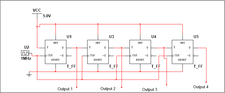
It consists of parallel arrangement of flip-flops wherein all the flip-flops are clocked simultaneously and in synchronization with the clock pulses. This is the reason propagation delay is independent of the number of flip-flops in the Synchronous counters.
These counters are equipped with combinational logic circuit as well, to ensure each flip-flop toggles at the right time. In synchronous counters, output of one flip-flop is given to input of another flip-flop.
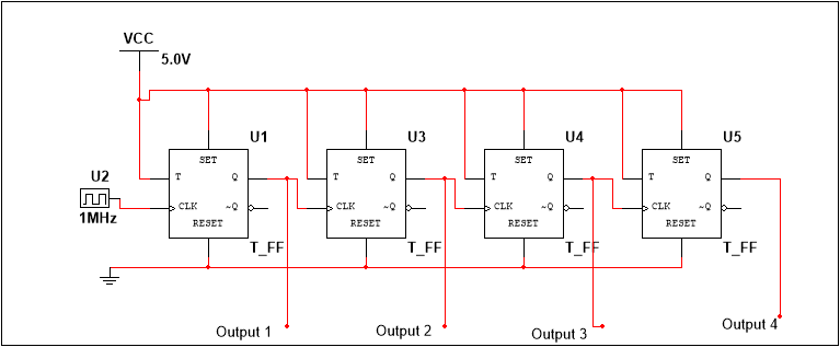
Asynchronous or Ripple Counters
Click image to enlarge
- Also read: 555 Timer
It consists of a cascaded arrangement of flip-flops wherein clock pulse of one flip-flop is driven by the output of its predecessor flip-flop. The number of flip-flops used determine the modulus of the counter, wherein the number of flip-flops depend upon the number of logic states in the counter, before it reaches its initial state.
The clock input is given to the first flip-flop. For a Modulo n counter, the clock input to the nth flip-flop is determined by the (n-1)th flip-flop output. Since clock of one flip-flop depends on the output of the previous flip-flop, it would change its state after a certain time delay which equals the propagation delays of both the flip-flops. For a Modulus n counter, the nth flip-flop will change its state after a delay of n times the propagation delay of one flip-flop.
Since the clock information ripples through the counter, it is known as a Ripple Counter. Also since the flip-flops do not change state in synchronization with the input clock, these counters are also known as Asynchronous counters.
Since the final output would depend upon the propagation delay of each counters, there is a limit to the clock frequency, which is given as:
![]()
Where N is the number of flip-flops, td is propagation delay of one flip-flop and Ts is the strobe pulse width. Note that the propagation delay varies within different types of flip-flops.
Classification of Electronic Counters Based on Uses
Up/Down Counters:
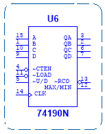 As the name suggests, these counters count in both ascending and descending order, i.e. in forward as well as reverse direction. While some counter ICs have separate clock input terminals for up and down counting (Example IC 74192 and IC 74192), some have only one clock input terminal and a control pin to select the required functioning (Examples: IC 74190, IC 74191).
Decade Counters:
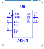
A decade counter or a Module-10 counter goes through 10 unique output combination states until it resets. It consists of 4 flip-flops and requires additional circuitry to skip few states, toconvert the normal counter to a decade counter. It can count 16 possible states, out of which only 10 are used. Examples are 4017B, 7490N.
BCD Counter:
 It is a special type of decade counter whose output is in accordance with the 8421 code. The counter states are the binary equivalent of decimal numbers. Example is 74LS90.
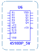
Presettable Counters:
These are counters which can be pre-set to any initial count, with the help of the PRESET and CLEAR pins of the Flip-Flops. The flip-flops can be clocked asynchronously or synchronously. Presettable counters can be UP counters, DOWN counters or UP/DOWN counters.
These consist of additional input/output pins such as ‘Preset’ (To load any desired count), Parallel Load (PL) inputs (allows PRESET inputs to be loaded to the outputs), and Terminal Count (TC) outputs (becomes active when terminal count is reached.). Examples are IC74190, IC4191 and IC74193.
Ring Counter:
This counter is developed by modifying a shift register. The true output of the last flip-flop is fed back directly to the data input of the first flip-flop, thus generating a sequence of pulses. For example, for a D Flip-Flop shift register, the Q output of the last flip-flop is connected to the D input of the first flip-flop. These counters are used in digital system to generate control pulses.
Johnson Counter
This counter is a reverse of Ring Counter. In other words, feedback from the last flip-flop is fed inversely to the data input of the first flip-flop. For example, for a D Flip-Flop shift register, the ~Q output of the last flip-flop is fed to the D input of the first flip-flop. These can be used as Divide by n counters as well.
- Note: You may read in more details about Ring Counters and Johnson Counters
Practical Counter IC 4017:
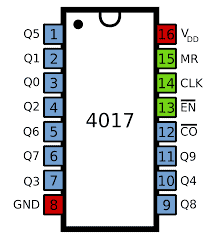
It is a 16 pin, CMOS logic Decade Counter cum Decoder, used mainly for low range counting applications. It can count from zero to ten, with decoded outputs, thus saving a lot of board space and time.
Functions of the IN/OUT PINS Of Counter IC 4017
Given below is the functionality of each of its pins.
Pins 1 to 7, 9 to 11: These are output pins of the IC, with each pin going high with corresponding decimal count. The status is as given below.
Pin 1: Goes HIGH when ‘5’ is the count.
Pin 2: Goes HIGH when ‘1’ is the count.
Pin 3: Goes HIGH when ‘0’ is the count.
Pin 4: Goes HIGH on count ‘2’.
Pin 5: Goes HIGH on count ‘6’
Pin 6: Goes HIGH on count 7.
Pin 7: Goes HIGH when count is ‘3’.
Pin 8: It is the ground pin, which is connected to LOW level voltage or to the ground.
Pin 9: Goes HIGH when count is ‘8’.
Pin 10: Goes HIGH when count is ‘4’.
Pin 11: Goes HIGH when count is ‘9’.
Pin 12: This pin is used for connecting with another Counter IC, to support larger counting order. Though we can achieve counts to 20 or more, by cascading multiple IC4017s together, it is advised not to cascade more than 3 ICs, in order to avoid occurrence glitches.
Pin 13: This is an Active LOW pin and is termed as the Disable pin. Once given a logic HIGH signal, it will disable the whole function of the IC, irrespective of the clock pulses.
Pin 14: This is the clock input pin. The input clock pulses are given to this pin and the count advances on rising or positive edge of the pulse.
Pin 15: This is the Active LOW reset pin, which once given a ‘HIGH’ logic signal would reset the IC.
Pin 16: This is the Power Supply pin which should be given a voltage from 3 Volts to 15 Volts.
- You may also read: Types of ICs. Classification of Integrated Circuits and Their Limitation
Applications/Uses of Counters
Electronic counters are used in many digital electronic devices especially in digital clock and multiplexing. Most of their applications are listed below.
- As object counters
- Parallel to serial data conversion logic circuits
- Analog to digital convertors.
- Digital clocks
- Frequency counters
- Frequency divider circuits. (Where the Input frequency divided by 2)
- Timers and Rate measurement. (Time circuits, Washing machines, Alarm clock etc)
- Digital triangular wave generator.
- Generating staircase voltage
This is a brief overview about different types of counters. Any other information regarding counters are welcome in the below section.
you may also read: