Programmable Logic Controllers (PLC) for Industrial Control
PLC – Programmable Logic Controllers for Industrial Control
PLC (Programmable Logic Controllers) are widely used in industrial and manufacturing automation systems for improved operational availability and extendable production rates.
As industry increasing its production rates without compromising product quality, PLCs are widely accepted by the industry so as to minimize the time and cost of developing a large quantity of products and also for developing new products. Applications of the PLCs vary from simple stand-alone installations to complex machine control.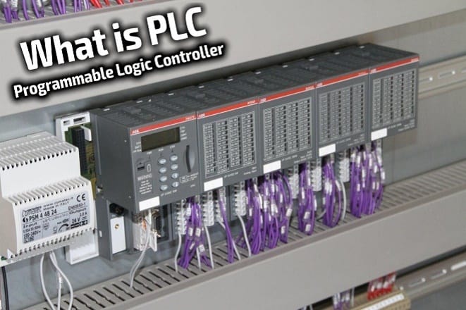
What is PLC (Programmable Logic Controller)?
Programmable Logic Controller (PLC) is a digitally operating electronic system or it can be termed as industrial computer which is designed especially for use in industrial environment. It can be easily integrated into the industrial control systems to expand and enhance the performance of industrial processes.
PLCs replaces the conventional relay logic control where a set of relays is hardwired to perform a specific task and also if the system needs any changes then relay wiring has to be modified accordingly.
PLCs overcomes such hardwiring associated with relay control circuits not only by performing such switching tasks, but also performing the operations like processing analog signals, counting, timing, sequencing, comparing, etc. The principle operation programmable logic controller is illustrated in figure below.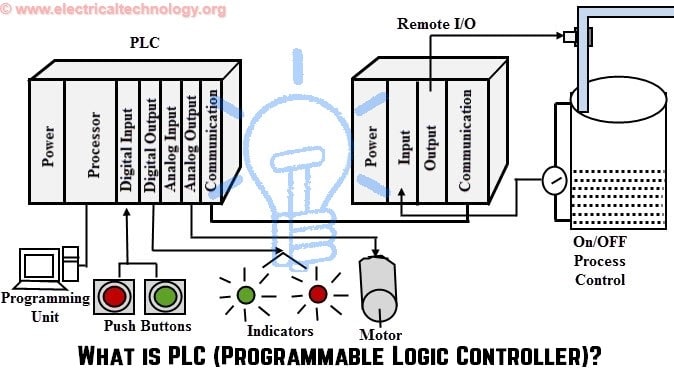
PLCs continuously monitors various sensor outputs connected to its input modules and produces output decisions to the actuators connected to output modules according to the control function implemented in its program.
Since the PLC has some memory, once the program is written, tested and downloaded to the PLC, it takes charge control of a process, thus increases the reliability.
A PLC can communicate with other PLCs or computers or any other smart instruments via a communication network to perform the functions like downloading of programs, remote monitoring the devices, facilitating supervisory control, etc.
Types of PLCs
PLCs can be placed into two categories, namely fixed and modular. Fixed PLCs are cheaper, smaller and easier to install. It consists of predetermined digital and analog modules (of a fixed number of channels) along with processor and power supply units.
For an expanding number of I/O channels, fixed PLC requires separate interconnectable components. However, modular PLCs offers flexibility to the user in order to match the controller components to the specific application needs. It has an extendable I/O capacity, larger memory size and communication with remote unit capability.
Parts of PLC
The components or parts of PLC are housed in a suitable cabinet designed especially for the industrial environment. The following are the main components of a PLC.
Power Supply Unit:
It converts AC mains voltage to PLC operating low DC voltage and supplies the power to the modules that are plugged into the rack. The specification of the power depends on the type of PLC being utilized in the application.
In some PLCs, power supply is the part of processor module that can deliver all required power to the system. In such cases, additional power source is needed if excessive current or voltage is required by some modules (analog and external communication modules).
In some PLCs, power supply is the separate module that can deliver a current greater than the sum of all currents needed by other modules.
Mounting Rack
It provides the means for mounting processor, I/O modules, communication modules and power supply module. It is a metal framework with PCB backplane consisting of several racks for all the modules.
These racks specify the number of modules that can be required to implement the system. The power and data connections are provided by these racks to the processor via the backplane. This rack also holds the power supply module if processor does not consist a power supply unit (inbuilt) as stated above. Modular PLCs can be extendable to large number of I/O modules because mounting racks are cascadable.
Processor or CPU
This unit consists of microprocessor, system memory, serial communication ports and LAN link. In some cases it consists of a power supply to deliver the necessary power to CPU and I/O modules. It is the brain of the PLC which executes the control logic (implemented on its program) by accepting the inputs from various I/O modules and then determines the appropriate output signals to output modules.
The CPU also consists of data and program memory, i.e., EPROM and RAM for storing instruction for logic control and for storing results of logical operations respectively.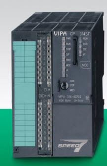
PLC Input/ Output (I/O) Modules
I/O modules interface the field devices (both input and output devices) in the control environment to the processor. These input devices include sensors, push buttons, limit switches, etc. and output devices include motors, relays, solenoid valves, etc. I/O devices fall into two major categories i.e., discrete or digital and analog modules.
Digital I/O modules can be individual digital input or output modules or a combination of both digital input and output points on same unit. Depending on the manufacture or the application requirement, each digital module has a number of channels like 8 or16 or 32 channels with specified voltage values (of only AC or only DC or AC/DC) for connecting a number of ON-OFF type inputs and outputs.
Similar to digital modules, analog I/O modules can be individual analog input or output modules or a combination of both analog input and output channels on same unit. These channels are specified with particular voltage or current range and desired resolution. The number of channels in each analog input or output module depends on the PLC’s manufacture.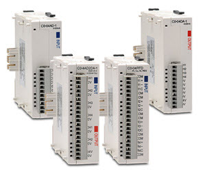
PLC Ladder Programming
The main advantage of a PLC is that it offers five different programming languages to program control logic for the application. These languages are instruction list (IL), structure text (ST), ladder logic diagrams or ladder logic (LD), sequential flow control and function block diagram.
Among these languages, ladder logic is the very common method of programming a PLC. This ladder diagram resembles hardwired relay logic diagrams.
Structure Ladder Programming:
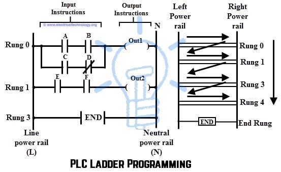
- The ladder diagram consists of two vertical lines called as power rails between which logic circuits are connected as shown in below figure. The left side rail is the line power rail (L) which resembles hot or live side of the power supply. The right side rail is the neutral power rail (N) which resembles common side of the power supply.
- The horizontal lines are called rungs which are connected between two vertical lines (power rails). Each rung provides electrical continuity between rails if there is uninterrupted electrical path. And also each rung specifies one operation in the control process.
- Each rung must start with one or more input instructions at L power rail side i.e., on rung left-hand side) and must end with one or more output instructions at N power rail side i.e., on rung right-hand side). These input and output instruction must have specified address in the memory for which notation depends on the PLC manufacture.
- A ladder diagram is executed or read from left to right and top to bottom as shown in figure. This means top rung is read from left to right and then next down rung from left to right and so on till end rung. This is termed as PLC cycle.

Basic Symbols used in PLC Programming
| XIC (Examine If Closed): True when its associated bit is at logic 1 state. | |
| XIO (Examine If Open): True when its associated bit is at logic 0 state. | |
| Invert: It inverts the power applied before it. | |
| One-shot rising contact: If the conditions change from OFF to ON before this contact, this passes the power for only one scan. | |
| Output: If any rung passes the power from left to right the output is energized otherwise de-energized. | |
| Set: If any rung passes power to the set output, it (set) remains energized even no power is passed through that rung. | |
| Reset: If any rung passes power to the reset output, it (reset) remains de-energized even no power is passed through that rung. |
Along with these input and output instructions, various functions like timers, counters, PID blocks, compare, move and arithmetic operation blocks in the PLC function library helps to create required control logic for the application.
Examples of Ladder Logic Diagrams for PLC
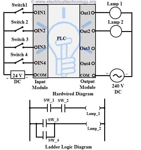
Example 1.
- The ladder logic diagram that turn ON switch 1 and switch 2 for controlling lamp1 and either switch 3 or switch 4 or both for controlling lamp2 is shown below along with wiring diagram.
Here in this example, switches are connected to the input module and lamps are connected to the output module. Processor gets these I/O address and depending on the logic program, it will drive the lamps.
The logic program for this example is given below in which switch 1 and switch are connected in logical AND fashion while switch 3 and switch 4 are connected in logical OR fashion.
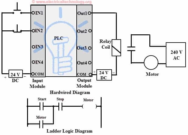
 Example 2.
- The ladder diagram for motor turn ON and OFF with emergency stop button using a relay and a PLC is shown below.

You may also read:
- SCADA Systems for Electrical Distribution
- What Exactly Is A Smart Grid? Smart Grid Applications
- High Inrush Current in Capacitor Switching and Ways to Prevent It.
- Integration of Renewable Energy with Grid System
- Fault Current Limiter and Their Types
- Why Nuclear Power is It The Last Option in Most Countries?


THIS SITE TAKES PRECEDENCE TO THE TEXTBOOK . GIVEN THE PRIVILEGE ACADEMIC RESEARCHES IS BETTER DONE USING YOUR AVALANCHE OF MATERIALS GENERATED HERE . I APPRECIATE .
hello
i am interessing by your components (plc)
so i want from you to send me news lettrs to my email to follow the news of your products .
Best regards
hassan haddouchi
email: haddouchimacz@gmail.com
tel 00 212 66 07 22 842
You may subscribe for free at the the top right side bar … Please subscribe and you will get each new post in your inbox free of cost. Thanks for appreciation….
The topics are most useful for new candidates who are anctious to learn in details.
Thanks for such notatiobs.
good article