Types of Transformers and Their Applications
Types of Electrical Transformers
What is a Transformer?
An electrical transformer is a machine that steps up or steps down the voltage level without changing the frequency of the power circuit. There are various types of transformers, including power transformers, distribution transformers, autotransformers, instrument transformers (current transformers and voltage transformers), and isolation transformers etc, used for different applications in both industrial and residential settings. We will discuss each type in detail below.
Different Types of Transformers
There are different types of transformer based on their usage, design, construction, etc. We will discuss some of these types in this article below;
Based on its Core;
Classification of transformer base on the material used for its core,
-
Air core Transformer
This type of transformer uses plastic or air as its core. The windings are either wounded around the plastic core or there is no physical core. The air has very low magnetic permeability. So there is no flux linkage between the coils as they are linked through the air between them.
The absence of Ferro-magnetic core (such as iron core) reduces the core losses, as these losses increase with the frequency. The ferromagnetic material also causes distortion in high-frequency signal. So the air core transformer is suitable for radio frequency current. Another positive point of air core transformer is that they are lightweight & they are suitable for mobile electronic devices such as radio transmitter etc.

-
Ferromagnetic/Iron Core Transformer
As the name suggests, these transformer’s core is made of ferromagnetic material. A ferromagnetic core is used in a transformer to increase its magnetic field. The strength of the magnetic field depends on the magnetic permeability of the material used. Iron is a common ferromagnetic material used in such transformers.
Iron core transformers are used for heavy load applications having low frequency such as power supplies. The iron core does include its frequency dependent core losses such as eddy current & hysteresis losses.
They are used for increasing or decreasing the AC voltage levels.
Based On Voltage Conversion:
Transformers are also classified based on its AC voltage level conversion.
Step Up Transformer
In such type of transformer, the voltage of its secondary winding is greater than the primary winding. This is because the number of turns in the primary winding is lesser than the number of turns in the secondary winding.

The output voltage of a transformer depends on its turn ratio which is given by;
Turn Ratio = Ns/Np
The turn ratio of a step up transformer is greater than 1.
As we know that the input & output power of a transformer remains the same. This implies that the step-up transformer increases the voltage but it also decreases the current from primary to the secondary winding. Thus it maintains a constant power.
Step up transformer are mainly used in power transmission over a long distance to reduce line losses (I2R). The line losses depend on current, so decreasing the current (while increasing voltage) using step-up transformer reduces the loss and provide efficient power transmission.
A microwave oven also utilizes a step up transformer to increase household voltage supply (110/220) into the range of 2000 Volts.
Step Down Transformer
A step-down transformer decrease the AC voltage i.e. the output voltage is lower than the input voltage. The number of turns in the primary winding is greater than the number of turns in the secondary winding.

The turn ratio of a step-down transformer is less than 1.
Most common step down transformers are used in decreasing the 11kv voltage from power lines to standard consumer voltage used for domestic appliances.
Every cellphone charger uses a step-down transformer to decrease the domestic supply voltage for rectification.
- Related post: Why is a Transformer Rated In kVA, Not in KW?
Based On Its Usage:
There are Four types of transformer based on its usage.
Power Transformer
These transformers are used in power transmission by stepping up & stepping down the voltages at the power generation plant for efficient transmission.
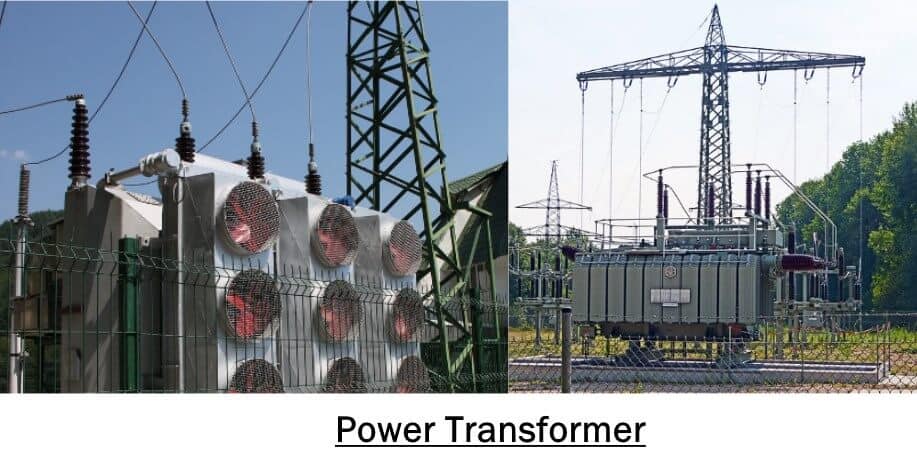
As we know that the line losses (I2R) depend on the current. In order to decrease the line current, we increase the line voltage using a step-up power transformer.
Their operating voltage is very high ranging above 33KV with power ratings of greater than 200MVA. They are huge in size and they operate at maximum load having 100% efficiency.
Related Posts:
Distribution Transformer
These transformers are used for the distribution of electricity to the household or commercial uses. They step down the high line voltages (>11Kv) into the standard domestic voltage (120/240 volts).
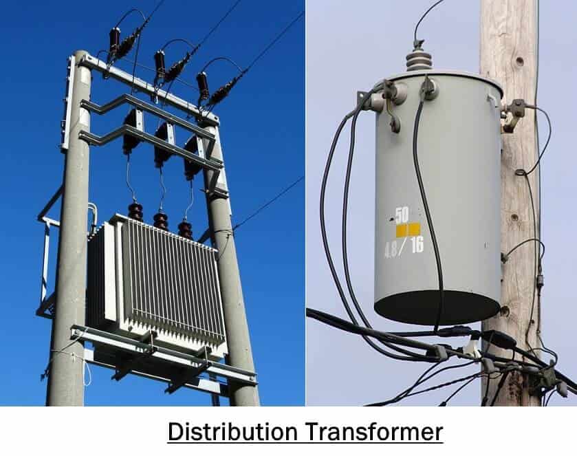
They are smaller in size as compared to power transformer and they are easy to install. They have low voltage & power ratings usually below 200MVA. Their efficiency remains below 70% because the never operate at full load.
- Related Posts:
Isolation Transformer:
Isolation transformers are used to electrically isolate a device from the power mains to prevent electrical shocks.

One end of the primary of the isolation transformer is grounded/earthed. In case, if someone touches a bare conductor on the secondary side, there will be no current flow. The circuit is incomplete because the earth will be at the same potential as that person.
The 1:1 turn ratio transformers are mainly used as isolation transformer but they can be designed as step up or step down transformers.
They are made with a special insulating material between winding that can support high AC voltages & due to its capacitive coupling it completely blocks any DC component.
There is a grounded Faraday shield between the windings that suppress any noise or interference.
They are used for safety measurements to prevent any electrical shocks or connecting two circuits that should not be connected electrically.
- Related Post: Power Transformer Protection & Faults
Instrument Transformers:
Such type of transformer is used in the measurement of high voltage and current.
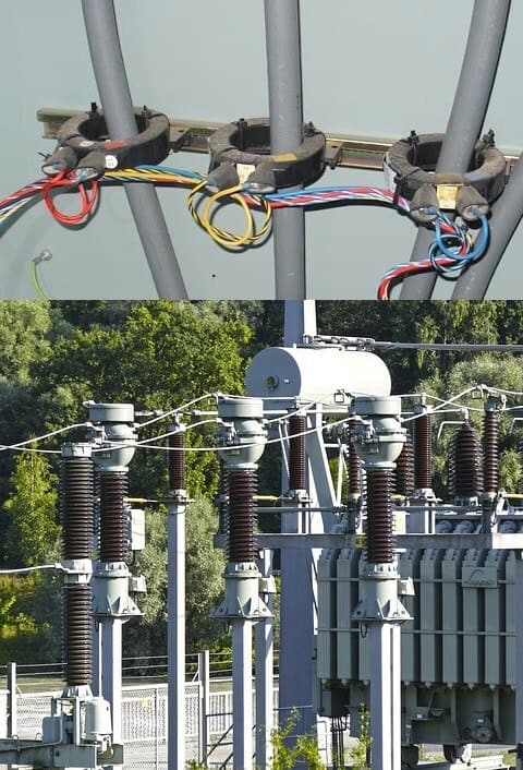
These transformers step-down the voltage and current down into a safe range, which is easily measured through typical measurement instruments.
There are two types of instrument transformers i.e. Current transformer & potential transformer.
Current Transformer
Current transformer, CT is used in the measurement of very large current. . Read a detailed post about Current Transformers (CT) – Types, Characteristic & Applications
Potential Transformer
Potential Transformer is also known as Voltage Transformer. It is used for measuring high voltages. To do so, the primary winding of the transformer is connected across the high voltage lines. On the secondary side, all the measuring tools and instruments such as meters are connected to measure and analyse the voltage level.
The primary winding is earthed or ground where potential transformer step up the value of voltage to a safe level.
Below are the different types of Potential transformers
- Electromagnetic: Wire Wound Transformer
- Capacitor Voltage Transformer (CVT): It uses capacitor voltage divider circuit
- Optical Transformer: Based on the electrical property of optical materials.
The Instrument transformer isolates the measurement circuit from the high power circuit to reduce the risk of getting shocked.
Based On Windings;
Transformers are divided into types based on the design of its windings.
-
Two Winding Transformer;
Such type of transformer has two separate windings for each phase i.e. the primary winding & secondary winding.

The primary winding is supplied with the AC input while the secondary is connected with the load.
These two winding are electrically isolated but magnetically coupled.
The EMF induced in the secondary winding is due to the changing magnetic flux caused by the varying current in the primary winding, also known as mutual induction. So the output voltage is purely due to induction.
The output voltage depends on the turn ratio of its both windings & it can increase or decrease the input voltage.
- Related Post: EMF Equation Of a Transformer
Autotransformer:
Autotransformer has only one winding per phase, which is divided into two parts i.e. primary & secondary winding.

The winding of autotransformer has 3 tap points, two of them are fixed while the third one is a variable tap point.
The variable tap point can be moved to increase or decrease the number of secondary turns. Thus increasing or decreasing the output voltage.
It can be used in either configuration to step-up or step-down the input current & voltage.
The output voltage can decrease (step-down), if the supply is connected to the fixed terminals. In reverse configuration that is if the supply is connected to the variable tap point, the output voltage will exceed the input (step-up).
The secondary winding is electrically connected to the primary, so there is no electrical isolation but it decreases the magnetic leakage flux.
The EMF in the winding is also induced due to self-induction. So the output voltage is the resultant of conduction & induction.
Based On The Insulation Used;
Dry Type Transformer:
This type of transformer does not contain any liquid cooling system. The windings are covered in epoxy resin to protect it from humidity. So the only cooling medium is Air.

As air is not a good insulator, so dry transformer use large coils & winding material to compensate for high temperature & ratings. This is why dry-type transformers are not available in the rating above 33KV.
Because of a poor cooling system, they tend to overheat which makes their lifespan short.
Furthermore, to ensure air circulation, regular inspection is required to maintain its working condition.
They are used in the in-door environment because they are less hazardous to catch fire. They are easy to install.
- Related Post: Transformer Performance & Electrical Parameters
Oil Immersed Transformer:
Such type of transformers utilizes combustible oil for cooling purposes. Oil offer better cooling than the dry type transformer which is why they are used for high rating transformers in harsh outdoor environments.

The disadvantage of this type of transformer is that they are large in size because of oil tank & the sensors required for the inspection of humidity etc. It contains flammable oil so they are not suitable for an indoor environment.
Based On Phase
Single Phase Transformer:
Single phase transformer is a two winding transformer having one primary winding & one secondary winding. The transformer is used for single phase application like Microwave oven, cellphone charger etc.
They have two input terminals connected with primary windings & two output terminals connected with the secondary winding.
Three Phase Transformer:
Three phase transformer has 6 windings in which 3 of them are primary winding & 3 are secondary windings for each phase. It has 12 terminals evenly divided on both sides (2 for each phase) considering star & delta connection. You can use 3 single phase transformer together instead of a 3-phase transformer.
They are used for power transmission & power distribution for domestics & commercial uses.
- Related Post: Advantages and Disadvantages of Three Phase Transformer over Single Phase Transformer.
Based On Core Design:
Based on the core design, transformers are divided into two types;
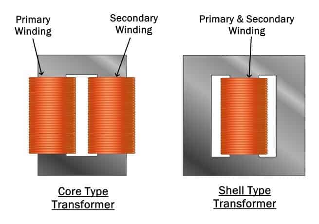
Core Type Transformer:
Such kind of transformer’s core is designed to have two limbs, each contains separate winding i.e. primary & secondary winding. The windings cover most of the area & it surrounds the core. The core is made of L shaped laminations in an almost square shape.
Their maintenance inspection is convenient compared to shell type because of its separate windings.
- Related Post: Transformer Phasing: The Dot Notation and Dot Convention
Shell Type Transformer:
Its core is made up of E & I shaped lamination in a rectangular shape having 3 limbs. Both windings are placed around the center limb on top of each other. The shell type core covers most of the area and surrounds the windings.
Berry Type Transformer
It is actually a shell type transformer but the name is related to the designer and its cylindrical shape. Berry type transformer has more than two independent magnetic circuits i.e. it has distributed magnetic circuits. The core construction of berry type transformer is like spokes of a wheal. The magnetic core and cylindrical windings are shown in fig below.
Related Posts:


This is a very informative website and proved to be an important resource centre for me as an electrical engineer.
Thanks for elaborating that power transformers are the ones that I see in my town and that they are responsible for stepping up or stepping down the voltages that a power generation plant generates. I’ve always wondered why we don’t have electricity in our town for a good week already until I saw that this type of structure seems like it had been broken by some hooligans, and the company who uses them hasn’t been notified about it yet. I guess this type of damage should be repaired by field experts since they might know how to reconnect the wires that they stripped off from it.