Classification of Electric Power Distribution Network Systems
Different Types of Electric Power Distribution Network Systems
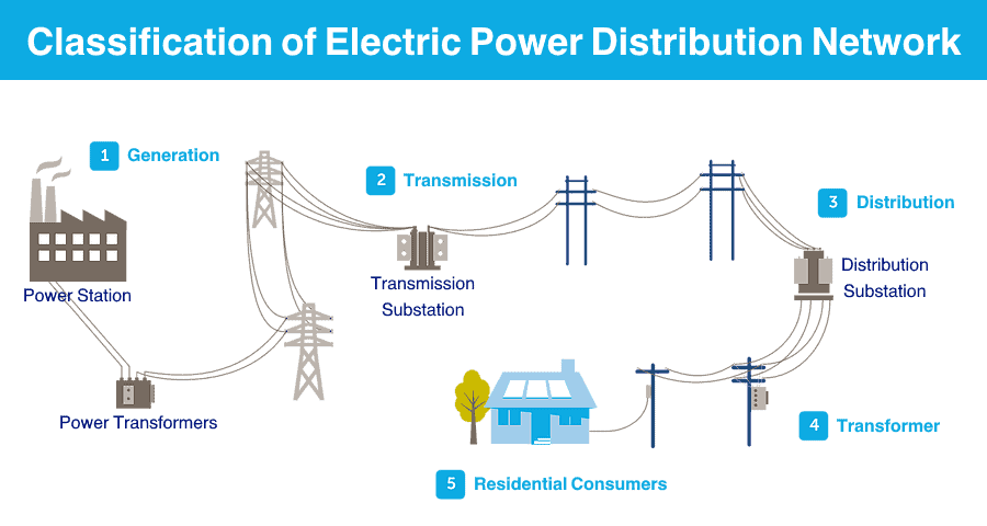
The typical electric power system network is classified into three parts;
- Generation
- Transmission
- Distribution
Electric power is generated in power plants. In most cases, power plants are placed far from the load centers. Hence, the transmission line is used to transmit power over a long distance.
To reduce the transmission losses, high voltage power is used in a transmission line. And voltage level is reduced at the load center. The power is distributed to load by a distribution system.
Types of Electric Power Distribution Systems
The distribution system is classified as below;
1) According to the nature of the supply
- AC Distribution system
- DC Distribution system
2) According to a type of connection
- Radial system
- Ring system
- Interconnected system
3) According to a type of construction
- Overhead system
- Underground system
Related Posts:
- Electric Power System – Generation, Transmission & Distribution of Electricity
- Electrical Transmission Networks – EHV and HV Overhead Lines
Let’s understand the classification of a distribution system in brief.
Classification According to Nature of Supply
There are two types of electric power; AC power and DC power. According to the type of power used in the distribution system, it is classified into AC distribution system and DC Distribution system.
AC Distribution System
In most of the conditions, the power consumer or load requires AC power. Therefore, the electric power is generated, transmitted, and distributed in the form of AC power. Because an AC voltage can be easily step up and step down with the help of a transformer.
According to the voltage level, the AC distribution system is further classified into two types;
- Primary distribution system
- Secondary distribution system
Primary Distribution System
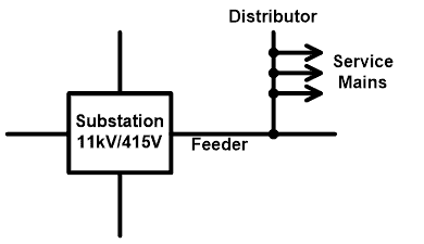
The voltage level of a primary distribution system is higher than the utilization voltage level. In most cases, the primary distribution system uses a three-phase three-wire system and the voltage level is in the range of 3.3 kV, 6.6 kV, and 11 kV.
The primary distribution system supplies power to big consumers like industries or large commercial complexes, etc. The voltage level is stepped down at the utilization level by a step-down transformer. This transformer is placed near to the consumer premises.
The typical arrangement of a primary distribution system is as shown in the figure below.
Related Posts:
Secondary Distribution System
In a secondary distribution system, the power is distributed at the utilization level. The primary distribution system ends with a transformer that is used to convert 11 kV to 415 V. And this power is directly distributed to the small consumers.
In most cases, the primary winding of this transformer is connected in delta connection and secondary winding is connected in star connection to provide a ground terminal. Therefore, the secondary distribution system uses a three-phase four-wire system.
Single-phase supply is taken by using any one phase with a neutral terminal that provides a voltage magnitude of 230V or 120V (according to country standards). For small shops and residential purposes, a single-phase supply is used.
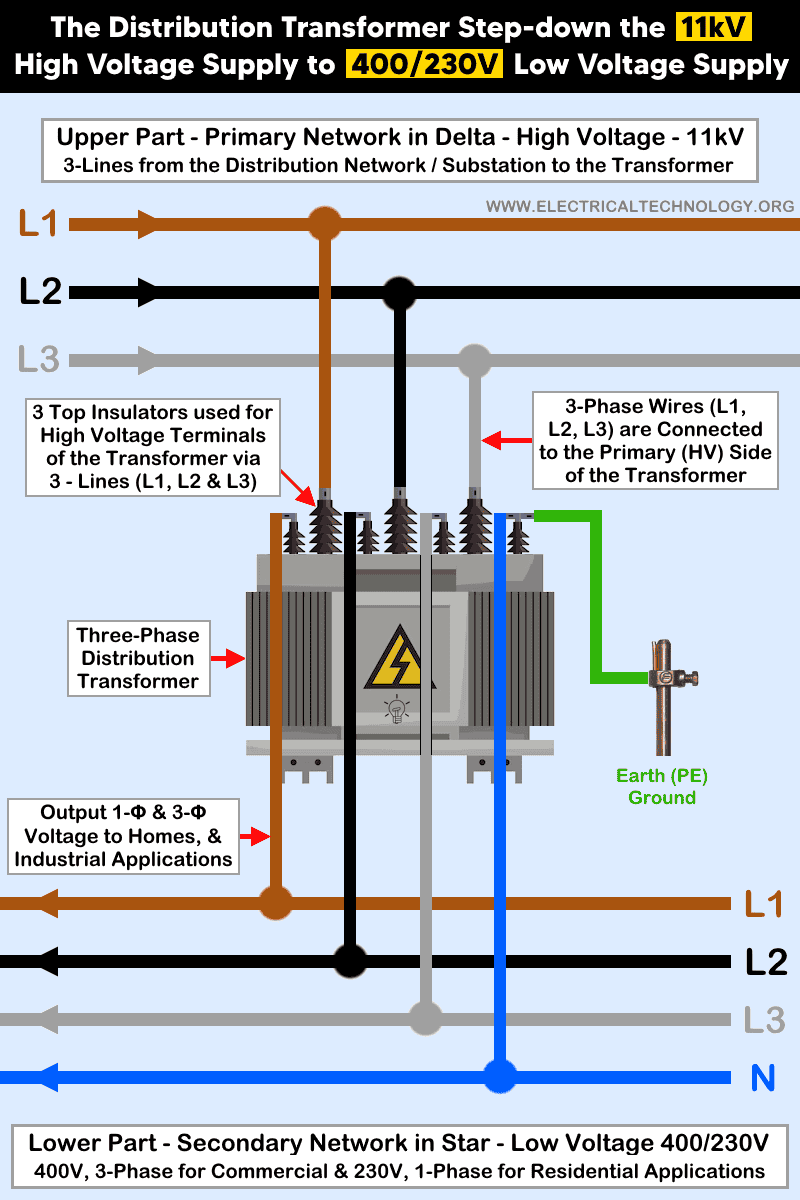
Some consumers require three-phase supply like small scale industries, flour mills, etc. This type of consumer uses a three-phase supply by using R, Y, B, and N terminals. The arrangement for the secondary distribution network is shown in the figure below.

DC Distribution System
Most of the load connected to the power system is AC load. But there is a certain application where we required DC power. To fulfill these applications, we use DC power in the distribution system and this system is known as the DC distribution system.
In this condition, generated AC power is converted into DC power with the help of a rectifier or rotary converter. The applications where we need DC power are; traction purpose, DC motors, Battery charging, and electroplating.
According to the connection of DC system, it is classified into two types;
- Two-wire DC distribution system
- Three-wire DC distribution system
Related Posts:
- Power System Restoration – Outage, Voltage Collapse & Switching Programs
- Comparison between AC and DC Transmission System
Two-wire DC Distribution System
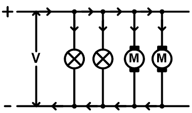
This type of distribution system requires only two wires; one wire is at a positive potential level and the second wire is at a negative or zero potential levels. The wire connected with a positive potential level is known as a healthy wire.
The load is connected in parallel between two lines. Generally, the load connected in this system is lamp-load or motors. The load has only two terminals can be connected in this type of system. The connection diagram of this system is shown in the figure below.
Three-wire DC Distribution System
This type of distribution system requires three wires; two wires are healthy wires and one wire is the neutral wire. The main advantage of this system is that we have two voltage levels in this system.
Let say, two healthy wires are at a voltage level of +V and -V. The neutral wire is at zero potential networks. If a load is connected between one healthy wire and a neutral wire, the available voltage is V volt. And if a load is connected between both healthy wires, the available voltage is 2V volt.
Hence, the load requires a higher voltage that is connected between healthy wires, and the load requires a lower voltage that is connected between one healthy wire and a neutral wire. The connection diagram of a three-wire distribution system is as shown in the figure below.

Related Posts:
- Internet of Things (IoT) and Its Applications in Electrical Power Industry
- FACTS – Flexible AC Transmission System – Types of FACTS Controllers & Devices
Classification According to Method of Connection
The distribution system is classified into three types according to the method of connection;
- Radial system
- Ring main system
- Interconnected distribution system
Radial System
In a radial system, a separate feeder is used to feed power from the substation to each area. And this feeder feeds power to a distributor in one direction only. The design of the radial system is simple and easy to implement in the system.
The initial cost of this system is less compared to other systems. But the reliability of this system is very low. If one feeder is out of step condition, the entire system will stop. This type of system is only used for a short-distance distribution system.
The consumer far from the feeder may suffer poor voltage regulation and voltage fluctuation with a variation of load. Due to this advantage, this type of system is only used to supply the load which is near to the feeder. The single line diagram of the radial system is shown in the figure below.
Ring Main System
In the ring main system, the distribution transformer is connected in a loop and supplied by a substation from one end. It means each distribution transformer has two different ways to connect with the substation. A single-line diagram of the ring main system is shown in the figure below.
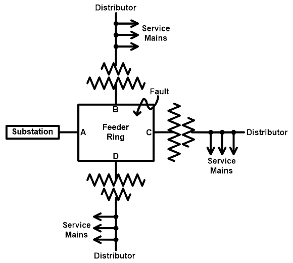
We can compare this arrangement with two feeders connected in parallel. For example, if a fault occurs between B and C points. In this condition, the part between B and C will isolate from the system. And substation supply power in two different ways.
It makes the system more reliable. And there is less voltage fluctuation at the consumer’s end. Each part of the ring carries less current. So, less conductor material is required compared to radial system.
Related Posts:
- What is HVDC? – High Voltage Direct Current Power Transmission
- Types of HVDC Systems and MTDC Configurations
Interconnected Distribution System
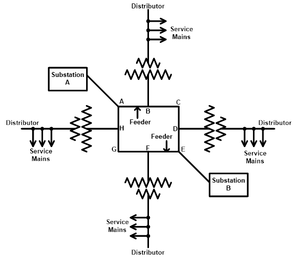
In an interconnected distribution system, a loop is supplied by more than one substation at different points. This system is also known as a grid distribution system. The single-line diagram of the interconnected system is shown in the figure below.
As shown in the above figure, loop ABCDEFGHA is supplied by two substations at points A and E. Due to this type of arrangement, the reliability of the system increases compared to the ring main and radial system.
The design of the interconnected system is very difficult and the initial cost of the system is also high as a greater number of substations are required in a system. But this system has the advantage of good power quality and a more efficient system. This system reduces reserve power capacity.
Classification of Distribution System According to Type of Construction
According to the construction of distribution system is classified into two types;
- Underground distribution system
- Overhead distribution system
Underground Distribution System
As the name suggests, in this type of system, the conductors are placed under the surface of streets or sidewalks. The underground distribution system is safer than the overhead distribution system. But the initial cost of the underground system is very high. Because it requires trenching, conduits, manholes, and special cables.
In this system, the cables lie under the streets. Hence, there are fewer chances of the fault and it gives a good appearance as cables are invisible. When a fault occurs in the underground system, it is difficult to locate and also it is difficult to repair. The life of an underground system is very long. The useful life of this system is more than 50 years.
Related Posts:
- Differences Between HVAC and HVDC – Power Transmission
- Advantages of HVDC over HVAC Power Transmission
Overhead Distribution System
In the overhead distribution system, the conductors are mounted on wooden, concrete, or steel poles. This system is also known as a conventional system for the distribution network. The conductor is placed on the poles, there are more chances of fault and hazards compared to the underground distribution system.
But the initial cost of the overhead system is less. The overhead transmission system is more flexible compared to the underground system. Because this system is permanently placed once installed. Hence, it is easy for load expansion and laying a new line. The conductors are placed over the surface. So, the appearance of this system is not good as an underground distribution system.
In the overhead system, the conductors are placed with taking proper space. Hence, the air is used as an insulation medium. So, it does not require special insulated cables. The current carrying capacity of the overhead system is higher compared to the underground system.
It is easy to install the overhead system. And also, when a fault occurs, it is easy to locate and repair a fault. Hence, the maintenance cost of the overhead system is very less. There are chances of interference with a communication system. The useful life of an overhead system is more than 25 years.
Related Posts:
- Why Electric Power Transmission is Multiple of 11 i.e 11kV, 22kV, 66kV etc?
- What Exactly Is A Smart Grid? Smart Grid Applications
- Integration of Renewable Energy with Grid System
- Why Power Plant Capacity Rated in MW and not in MVA?
- Failures In Electrical Systems, Equipment & Materials
- Effect of Harmonics on Power System
- HV And MV Switch Disconnectors And Isolators in Power System
- Primary and Secondary or Backup protection in a Power System
- Corona Effect & Discharge in Transmission Lines & Power System
- Design and Installation of EHV/EHV and EHV/HV Substations
- Busbars and Connectors in HV and EHV installations


Commercial and industrial facilities require electrical systems that can handle high loads and complex operations.