Difference Between Ideal and Real or Practical Transformer
What is the Difference Between Ideal Transformer & Practical or Real Transformer?
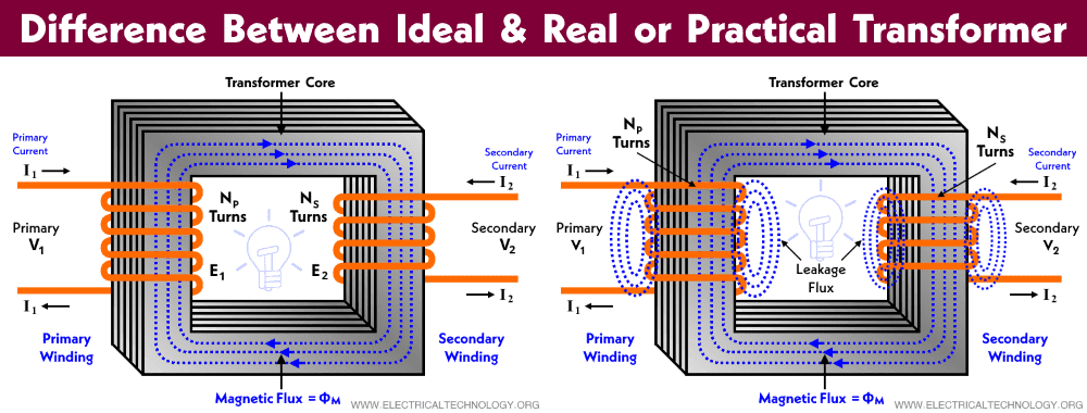
An ideal transformer is a theoretical model of a practical transformer without losses. In short:
- Transformer + 0% losses = Ideal Transformer
- Transformer + Losses = Practical Transformer
Let’s discuss what is the main difference between them.
What is an Ideal Transformer?
An ideal transformer is no more but an imaginary like a theoretical model which doesn’t exist in real life with practical applications. It has zero losses at all having 100% efficiency which is only used to represent the current and voltage transformation ratio of the practical transformer while analyzing circuits related to it.
The ideal transformer has the following assumptions
- There are no losses in the transformer (Leakage, ohmic, iron core (I2R as eddy current & hysteresis losses) etc.
- There is no leakage flux or leakage inductance.
- 100% efficient e.g. Input = Output.
- The core permeability is infinite.
The schematic diagram of the ideal iron-core transformer is shown in the figure below.
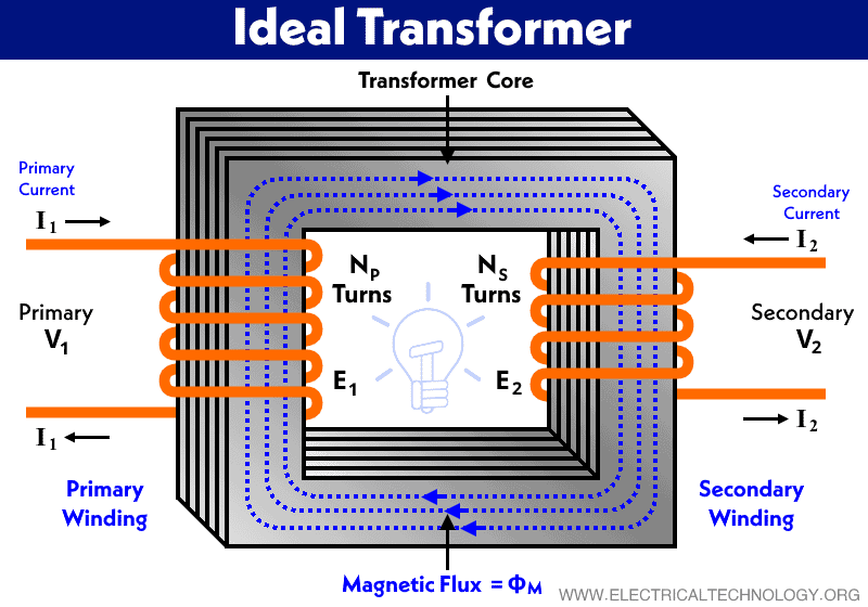
According to Lenz’s law, E1 is equal and opposite to V1.
E1 = –V1
The below figure shows the phasor diagram of an ideal transformer.

The transformation ratio also known as turns ratio “a” for an ideal transformer is defined as below equations.

Where,
- a = Transformation ratio
- T1, T2 = Number of turns in primary and secondary winding
- E1, E2 = Induced EMF
- V1 = Supply voltage (primary voltage)
- V2 = Secondary Voltage
- I1, I2 = Current passes through the primary and secondary winding
From the above equations, we get
I1T1 = I2T2
similarly;
E1I1 = E2I2
Hence:
S1 = S2
In other words; the input apparent power is equal to the output apparent power.
Input Apparent Power = Output Apparent Power
Keep in mind that ideal transformer doesn’t exist in real life applications and these assumptions are only applicable to an ideal transformer and all of the above mentioned points are not valid for practical transformers.
Related Posts:
- Difference Between Single Phase and Three Phase Transformer
- Difference Between Power Transformers and Distribution Transformers?
What is a Real Transformer?
If we relax these assumptions (mentioned and applicable only for the ideal transformer above) one by one, we will arrive at the model of a practical or real transformer. In other words, losses occur in a real or practical transformer (aka practical transformer or actual transformer).
Let’s consider a practical transformer having winding resistance and leakage reactance as follow:
Winding Resistance
The equivalent circuit of the transformer after adding resistance in the circuit is shown in the figure below. Due to the voltage drop because of added resistances, this way, the secondary terminal voltage V2 is less than the secondary induced EMF E2 by an amount of secondary voltage drop I2R2 as V2 ≠ E2 and supply voltage V1≠E1. Therefore;
V2 = E2 – I2R2

Same is the case for primary induced EMF E1 is equal to the vector difference of supply voltage V1 and primary voltage drop I1R1.
E1 = V1 – I1R1
Leakage Reactance
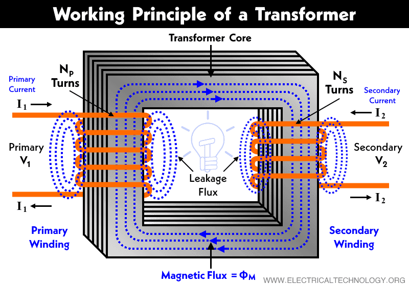
The flux generated in the winding of actual transformer passes completely through the core and links both windings is called mutual flux ФM. The typical diagram of fluxes in a transformer is shown in the figure for real transformer above.
Due to the leakage flux ФL1 and ФL2, the induced EMF EL1 and EL2 are different from induced EMF E1 and E2 caused by the mutual flux ФM. The representation of leakage reactance (X1 and X2) is shown in the figure below.
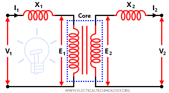
Where,
- X1 = Primary leakage reactance
- X2 = Secondary leakage reactance
Related Posts:
- Advantages of a Three Phase Transformer over a Single Phase Transformer
- Advantages of Three Phase System Over Single Phase System
Key Differences between Ideal & Real Transformers
The following table shows the main differences between an ideal & Real transformer.
| Characteristics | Ideal Transformer | Practical / Real Transformer |
| Existence | Imaginary – Doesn’t exist. | Exists in real life for practical applications |
| Efficiency | = 100% | > 100% |
| Losses | No | Yes |
| Inductive Material | Pure Inductive Material | Pure 2 Set of Inductive Materials |
| I2R losses | No | Yes |
| iron loss & Core losses | No | Yes |
| Core Permeability μC | Infinite (∞) | Finite |
| Core Reluctance | Zero | Lower |
| Leakage Flux ΦC & Reactance | No | Yes |
| Ohmic Resistance drop | No | Yes |
| Condition | Ideal | Practical |
| Applications | Not practical uses, but only to analyze circuits to represent the current & voltage transformation ratios. | Practically used in real life applications such as step-up or step-down the level of current or voltage for utilization. |
Related Posts:
- Applications of Transformers
- Parallel Operation of Single-Phase & Three-Phase Transformers
- Open Circuit and Short Circuit Test of a Transformer
- Sumpner’s Test or Back-To-Back Test on Transformer
- Scott-T Connection of Transformer
- Polarity Test of a Transformer – Circuit Diagram and Working
- EMF Equation of a Transformer
- What is the Transformer’s Voltage Regulation?
- Transformer Efficiency, All day Efficiency & Condition for Maximum Efficiency
- The Dot Convention and Dot Notation in a Transformer Phasing
- Transformer Performance & Electrical Parameters
- Power Transformer Protection and Faults
- Transformers Fire Protection System – Causes, Types & Requirements
- Can We Replace a 110/220 Turns Transformer with 10/20 Turns?
- Electrical Transformer Symbols – Single Line Transformer Symbols
- Can We Operate a 60Hz Transformer on 50Hz Supply Source and Vice Versa?
- Which Transformer is More Efficient When Operates on 50Hz or 60Hz?
- Transformers (MCQs With Explanatory Answers)