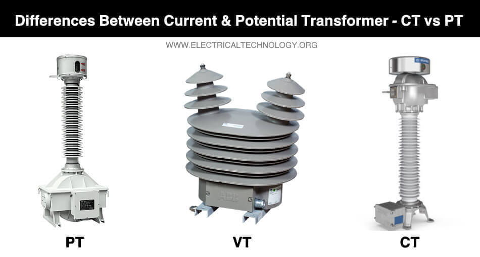
Difference Between Current Transformer & Potential Transformer
What is the Difference between Current Transformer and Potential or Voltage Transformer?
The voltage and current used for electrical power transmission over long distances is very high. Measurement of such current and voltage is impossible using our conventional meters. Therefore, Instrument transformers such as current transformers and potential transformers are used to decrease their levels down to safe limits where they can be measured with a normal meter.
Before going into the list of differences between current transformer and potential transformer, let’s explain them first.
What is a Transformer?
A transformer is an electrical device that transfers electrical energy from one circuit to another through mutual induction. It has two coils i.e. primary and secondary that are magnetically coupled and electrical isolated. They are used for increasing or decreasing the voltage and current levels without changing it frequency.
There are different types of transformers used for specific applications such as power transformers, auto transformer, isolation transformer, instrument transformer etc. The current transformer and the potential transformer are the two types of instrument transformer that are solely used for the measurement of high current and voltages in the power lines.
Related Posts:
- Difference Between GFCI and AFCI
- Differences Between HVAC and HVDC – Power Transmission
- Difference Between Series and Parallel Circuit – Comparison
Current Transformer
A current transformer (CT) is a type of instrument transformer that is used for reducing high current down to low level for measuring with normal Ammeter. It is used for the measurement of high current in power lines.

A current transformer is a step-up transformer that reduces the current but increases the voltage. It decreases the current down to few amperes. This current can be easily measured with our conventional Ammeter. But the voltage at its secondary is very high due to which the secondary of the CT must not be open when there is a current flowing through its primary.
It is connected in series to the power line whose current needs to be measured.
Potential Transformer
A Potential transformer (PT or VT) is a type of instrument transformer that reduces the high voltage down to a low level for measuring with a normal voltmeter. It is used for the measurement of high voltage in power lines.
A PT is a step-down transformer that decreases the high voltage that ranges in 100s kV down to 100-220 volt. This voltage can be easily measured with the conventional voltmeter. Due to low secondary voltage, the secondary terminals of PT can be left open.
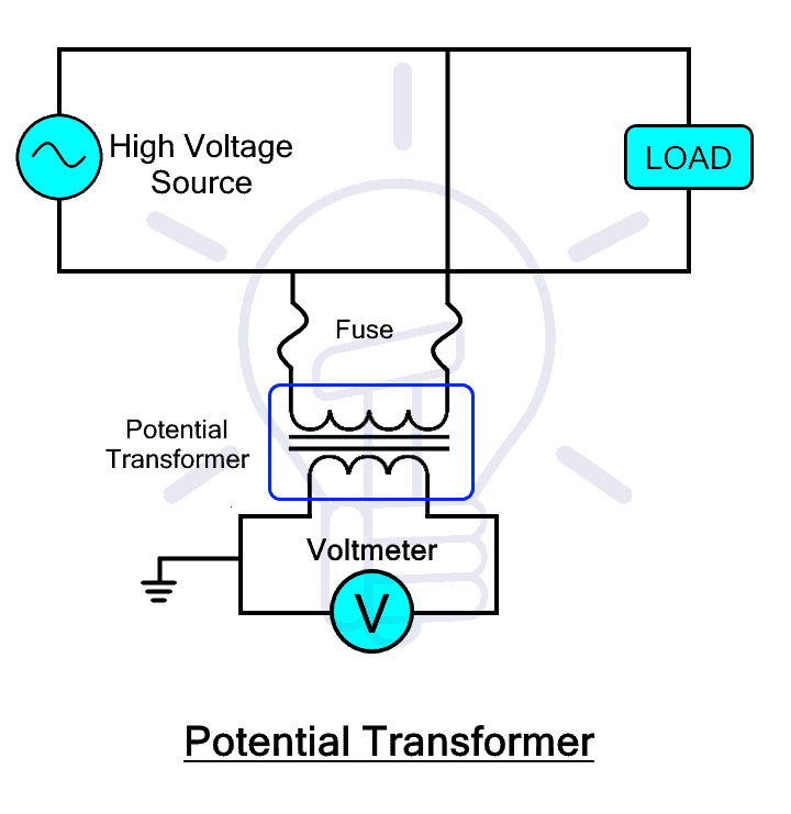
Apart from voltage reduction, the PT can also provide isolation between the high voltage line and the low voltage measurement circuit.
There are two types of a potential transformer; a conventional electromagnetic type transformer and capacitive potential type transformer. The former has a very high insulation cost due to very high voltage while the latter uses the capacitor circuit to divide the voltage before feeding it to the transformer.
Related Posts:
- Difference Between Grounding, Earthing and Bonding
- Difference Between Single Phase & Three Phase Induction Motor
- Difference Between Single Phase and Three Phase Power Supply
Comparison between Current Transformer and Voltage or Potential Transformer
| Current Transformer (CT) | Potential Transformer (PT or VT) |
| CT step-down the high current to the safe level of current. | PT step-down the high voltage levels to the safe level of voltage. |
|
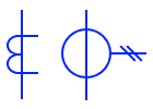
Symbol of CT
|
Symbol of PT or VT
|
| Its primary winding is connected in series with the line to be measured. | Its primary is connected in parallel to the line to be measured. |
| It has a fewer number of turns in its primary winding. | It has a large number of turns in its primary winding. |
| It has a large number of turns in the secondary winding. | It has few numbers of turns in the secondary winding. |
| Its secondary cannot be open circuit. | Its secondary can be open circuit. |
| It has a very high turn ratio. | It has a very low turn ratio. |
| Its accuracy does not depend on the secondary burden (numerous ammeters can be connected to output). | Its accuracy depends on the secondary burden and causes an error when numerous voltmeters are connected. |
| The primary winding contains full line current. | The primary windings contain full line voltage. |
| Current transformer can be either wound type or core type. | The potential transformer can be either electromagnetic or capacitor voltage type. |
| The primary current does not depend on the secondary current. | The primary current depends on the secondary current. |
| It is a step-up transformer. | It is a step-down transformer. |
| It is used for measurement and monitoring of current in high power lines. | It is used for the measurement of high voltage in power lines. |

Related Posts:
- Difference between Analog and Digital Multimeter
- Difference Between a Battery and a Capacitor
- Difference between Electron Current and Conventional Current
Important Differences
Function
- A current transformer function is to reduce the high current in power lines.
- A potential transformer function is to reduce the high voltage of power lines.
Connection
- A Current Transformer is connected in series with the power line so all the current flows through it.
- A potential transformer is connected in parallel to the power lines so all the voltage appears across it
Turn Ratio
- The current transformer has a very high turn ratio.
- The potential transformer has a very low turn ratio.
Number of turns in windings
- In CT, the number of turns in the primary is far less than the number of turns in the secondary windings.
- In PT, the number of turns in the primary is far more than the number of turns in the secondary winding.
Input
- The input of the current transformer is a constant current that flows through the power line.
- The input of a potential transformer is a constant voltage across the power lines.
Output
- The output of the current transformer ranges between 1 to 5 amperes.
- The output of the potential transformer ranges between 100 to 220 volts.
Secondary terminals precaution
- In CT, the terminals of secondary winding cannot be left open as there is a very high voltage gradient between them. It allows short circuits.
- In PT, there is a very low voltage at its secondary; therefore, it can be left open. But it should not be short-circuited.
Types
- The two types of CT are wound type and core type transformer.
- The two types of PT are electromagnetic and capacitor voltage types.
Core
- The core of CT is made of a lamination of steel.
- The core of PT is made of high-quality steel that operates at a very low flux density.
Secondary Burden
The burden is the number of components connected to the secondary of the transformer without affecting its accuracy.
- The CT is not affected by the secondary burden as the primary current does not depend upon the secondary current.
- The PT depends on the secondary burden as the primary current varies with the secondary current.
Applications
Apart from isolating the measurement instrument or multimeter from high power lines, they are used for;
- The CT is used for measurement of current and monitoring of high power lines to observe any abnormalities. They are also used for operation protective relays.
- The PT is used for the measurement of high voltages
Related Posts:
- Difference between Analog and Digital Circuit – Digital vs Analog
- Difference between AC and DC (Current & Voltage)
- Difference Between Alternator and Generator with Comparison
- Difference between Inverter & UPS – Uninterruptible Power Supply
- Difference Between Overcurrent, Overload and Overvoltage
- Difference between Lightning Arrester and Surge Arrester
- Difference between AC Drives and DC Drives
- Difference Between EMF and MMF
- Difference Between Voltage and EMF?
- Difference Between a Transformer and an Induction Motor
- Difference Between Active and Reactive Power – Watts vs VA
- Difference Between MCB, MCCB, ELCB & RCB, RCD or RCCB Circuit Breakers


