Wiring a Fast AC Level 2 EV Smart Breaker Charger Using Direct Connect and Junction Box Kits for 32A Electric Vehicle Charging
Green Motion EV Smart Breaker Charger
As traditional vehicles are being replaced by electric vehicles (EVs), modern homes increasingly require a dedicated EV charging point. While rising fuel prices have encouraged EV adoption, high electricity rates can also increase charging costs. To address this challenge, one of the simplest and most cost-effective solutions is to install a Level 2 EV smart breaker charger.
With a Level 2 EV smart breaker charger, you can conveniently charge your vehicle at home wherever it is parked while avoiding unnecessary energy costs. The charger can be monitored, controlled, and scheduled remotely through a smartphone app. It can be control remotely from anywhere to optimize charging times based on utility rates. In addition, the Fast AC smart charger can be configured to pause charging during peak-rate periods and automatically resume charging during off-peak hours when electricity is less expensive. This helps reduce overall charging costs while ensuring your vehicle is ready when needed.
Hardwiring an EVSE (Electric Vehicle Supply Equipment) is generally more reliable than using a plug-in connection. A hardwired installation provides a permanent electrical connection, reduces potential points of failure, and helps ensure long-term performance and safety.
The Green Motion EV Smart Breaker Charger by Eaton is a 7.7 kW, 32A Level-2 EV charging kit which can be wired directly or with junction box . The kit with 25 ft cable can be installed directly into compatible Eaton BR loadcenters or PRL3X panelboards. The charger combines thermal-magnetic circuit breaker protection, GFCI protection, automatic fault reset, and SAE J1772 EV charging functionality into a single device.
In the following wiring and installation guide, we will use the Eaton Green Motion EV Smart Breaker Charger with required wiring connections, installation procedures, and safety considerations as per codes.
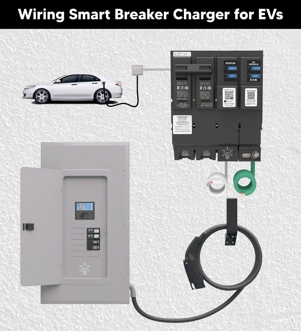
Good to Know: The EV Smart Breaker Charger is designed for use with plug-in hybrid electric vehicles (PHEVs) and is compatible with all electric vehicles (e.g. Tesla, Lucid, Rivian) that support the universal J1772™ charging connector, in accordance with the SAE J1772 charging standard established by the SAE International.
Electrical Ratings & Specifications
- Name: Green Motion EV Smart Breaker Charger by Eaton (BREVEM2040 & BABEVEM2040)
- Voltage: 208-240V AC – 60 Hz – Single-Phase
- Breaker Rating: 40A
- Charging Current: 32A
- Output Power: 7.7 kW at 240V, 6.6kW at 208V
- GFCI: 20mA Ground Fault Protection
- Connector Type: SAE J1772
- Wireless Connectivity: Smart Control through IEEE 802.11 b/g/n and 2.4 GHz Wi-Fi
- Listed: UL, CSA, NFPA Article 625, SAE J1772 2010 Ed., FCC Compliant, Part 15 and ANSI C12.20
- Wiring Method: Hardwired – Direct Connect and Direct Connect kit with Junction Box
- Compatible Enclosure: BR Loadcenter and PRL3X Panelboard
Click image or open in a new tab to enlarge
Before Installation …
Warning
- Make sure to de-energize all power sources before beginning installation.
- Installation must be performed only by a qualified electrician.
- Install in accordance with NEC Article 625 and all applicable local codes.
- The smart EV charger beaker should be used only for plug-in electric vehicles (PEV).
Code Requirements:
NEC 210.19(A)(1) specifies that conductors supplying continuous loads shall have an ampacity not less than 125% of the maximum load. In practical terms, this means that circuit breakers should not be loaded to more than 80% of their rated capacity when supplying a continuous load (defined as a load expected to run for 3 hours or more).
This is why the charger breaker rating is 40A while it is used for 32A of continuous charging load.
40A × 80% = 32A
The smart charger breaker is a dedicated circuit used for EV charging and it should not be used/shared with other load types as per NEC – 625.41
According to NEC Article 625, the coupling means (charging connector) of Electric Vehicle Supply Equipment (EVSE) must be stored or mounted within a specified height range to ensure accessibility and protection from physical damage.
- Indoor installations: The charging connector shall be stored or located at a height of not less than 18 inches (450 mm) and not more than 4 ft (1.2 m) above the floor.
- Outdoor installations: The charging connector shall be stored or located at a height of not less than 24 inches (600 mm) above the finished grade level.
GFCI & Grounding
NEC Section 625.54 requires ground-fault protection for electric vehicle supply equipment (EVSE). Since the EV Smart Breaker Charger incorporates a built-in Ground-Fault Circuit Interrupter (GFCI), a proper equipment grounding connection is required for safe and reliable operation. For this reason, the EV Smart Breaker Charger must be connected to a permanently grounded wiring system.
EV Connector Conductor Identification
The EV charging cable contains five conductors with different wiring color codes and functions:
- Red = Line 1 (L1) – Hot 1
- Black = Line 2 (L2) – Hot 2
- Blue = +12 VDC
- Orange = J1772 Pilot
- Green = Equipment Grounding Conductor (EGC)
Note: The orange pilot conductor is intentionally 1 inch shorter than all other conductors and this length difference must be maintained to comply with NFPA 70 Article 625.19.
Good to Know: These wiring tutorials applies to Eaton Green Motion EV Smart Breaker Chargers (BREVEM2040 & BABEVEM2040) and associated models GMEV32BR-DC, GMEV32BAB-DC, GMEV32BR-JB, and GMEV32BAB-JB (For both plug-on and bolt-on installation).
Method 1: EV Direct Connect Installation
This method is used when the EV charger cordset can reach the parked vehicle directly from the loadcenter or panelboard. As the vehicle can be charged close to the panel, the conductor size is 10AWG for L1, L2, Ground and 18AWG for J1772 pilot and +12VDC for 32A charging with 40A breaker.
Click image or open in a new tab to enlarge
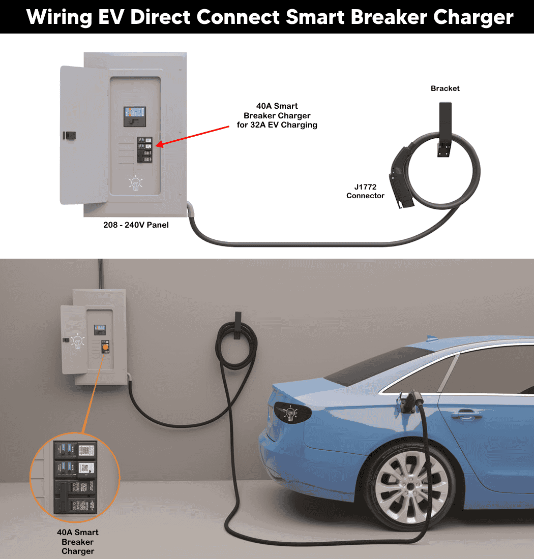
The Direct Connect Kit includes the following components which can be easily wired in compatible Eaton BR loadcenter or PRL3X panelboard.
- EV Smart Breaker Charger
- J1772 EV Connector with 25-foot cordset
- Cord Management Bracket
- ¾-inch NM/SE Connector
Step 1 – Disconnect Power
- Turn OFF the main power supplying the loadcenter.
- Verify absence of voltage using appropriate test equipment.
- Remove the loadcenter deadfront cover.
- Ensure the EV Smart Breaker Charger handle is in the OFF position.
Step 2 – Install the EV Smart Breaker Charger
- Make sure there are adjacent 4 empty slots inside the panel as the breaker occupies 4 spaces.
- Connect the white neutral pigtail from the charger to the neutral busbar.
- Connect the green grounding pigtail to the grounding busbar.
- Install the breaker charger into the designated location:
- BR Type: Plug onto the line bus.
- BAB Type: Bolt onto the line bus.
- Tighten all connections according to manufacturer torque specifications.
Click image or open in a new tab to enlarge
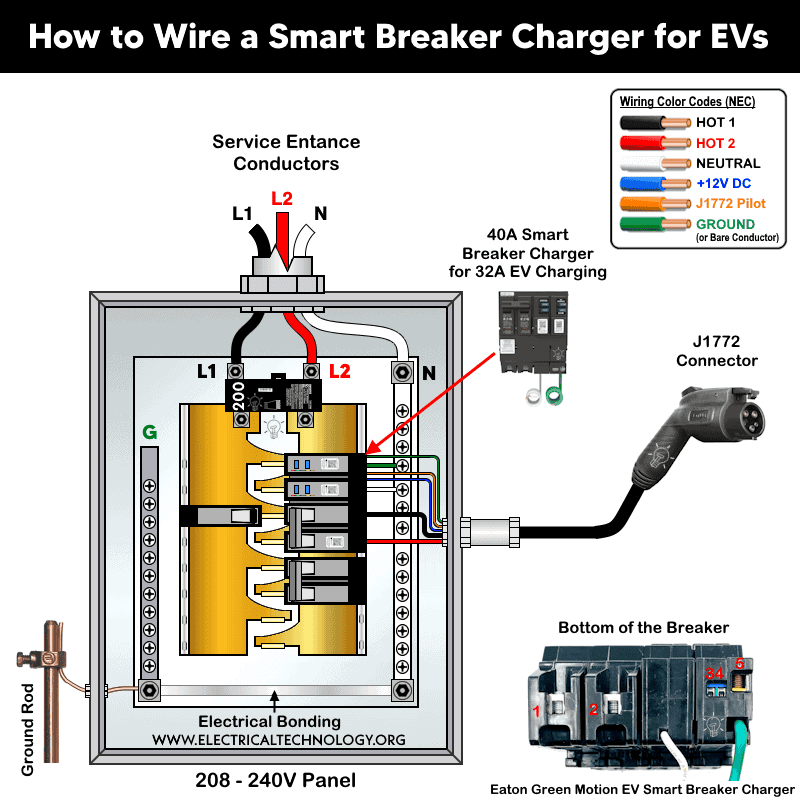
Step 3 – Route the EV Connector Cord
- Remove an appropriate knockout in the loadcenter.
- Install the supplied ¾-inch NM/SE connector.
- Route the EV connector cord through the connector.
- Secure the cord with the NM/SE locknut.
Step 4 – Connect the EV Connector Conductors
Terminate the EV connector conductors directly to the EV Smart Breaker Charger terminals:
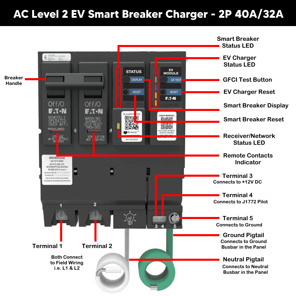
| Charger Terminal | Wire Color | Function |
| Terminal 1 | Red | Line 1 |
| Terminal 2 | Black | Line 2 |
| Terminal 3 | Blue | +12 VDC |
| Terminal 4 | Orange | J1772 Pilot |
| Terminal 5 | Green | Ground |
Ensure all conductors are securely terminated.
Step 5 – Reassemble and Energize
- Reinstall the loadcenter deadfront.
- Restore power to the loadcenter.
- Verify that charger electronics power up.
- Confirm EV connector LEDs illuminate.
- Move the EV Smart Breaker Charger handle to the ON position.
Method 2: EV Smart Breaker Charger with Junction Box Kit
This method is used when the vehicle parking location is farther away from the loadcenter. A junction box allows the charging cable to be installed up to 250 feet from the panel.
Click image or open in a new tab to enlarge
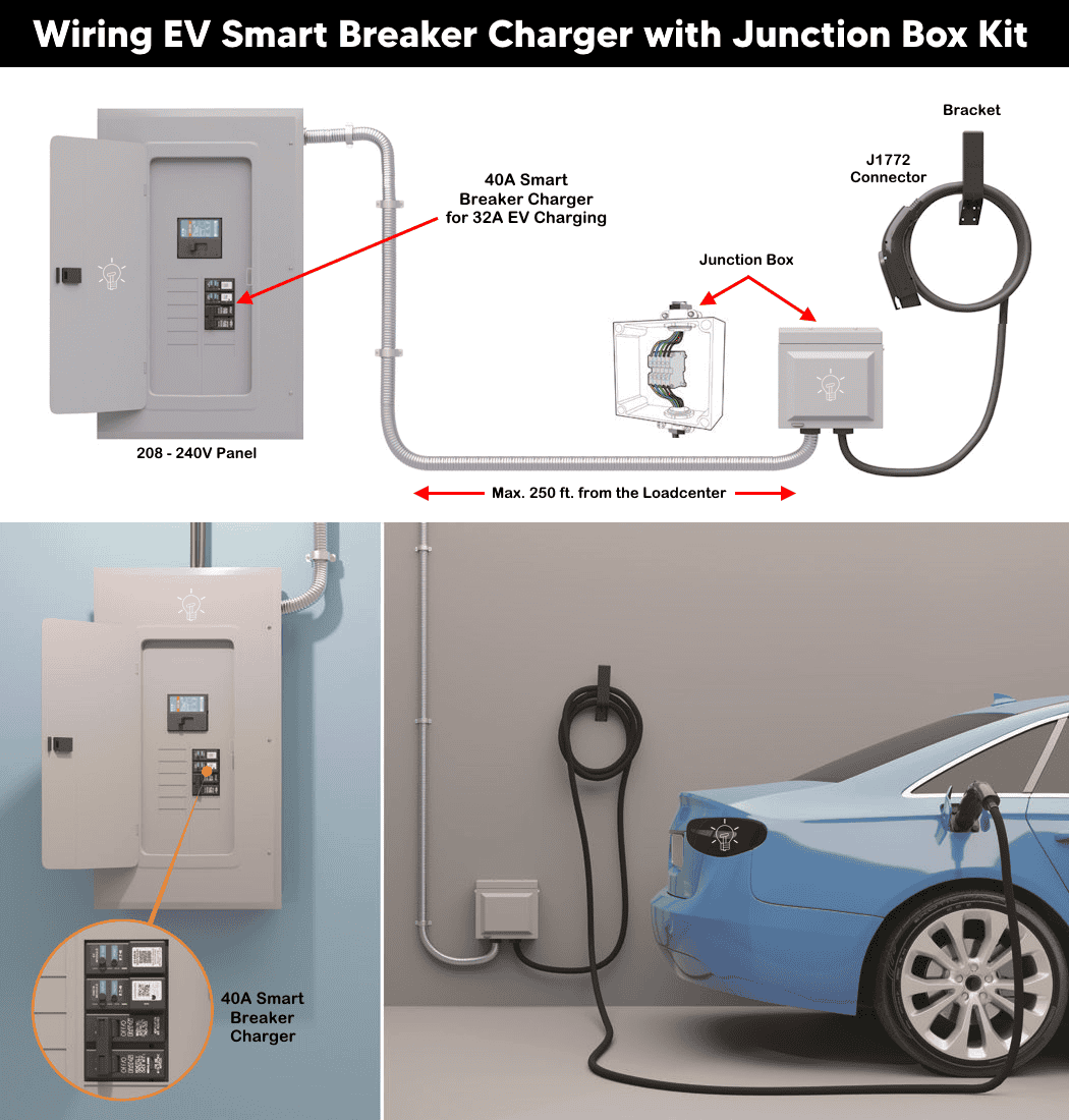
The following conductor sizes (AWG) should be used when wiring the EV Smart Breaker Charger through a junction box. The required wire size depends on the installation method and whether the conductors are installed above ground or underground.
| Conductor | Wire Size in AWG | |
| Up to 150 ft | Up to 250 ft | |
| Line 1 (Red) | #8 AWG Cu | #6 AWG Cu |
| Line 2 (Black) | #8 AWG Cu | #6 AWG Cu |
| +12 VDC (Blue) | #18 AWG | #18 AWG |
| J1772 Pilot (Orange) | #18 AWG | RG6 Quad Shield AWG18 |
| Ground (Green) | #10 AWG Cu | #10 AWG Cu |
All conductors must be rated 90°C at 600V copper. In case of Eaton junction box, remove the L1/L2 terminal blocks to accommodate even bigger size i.e. 6 AWG. If using coaxial cable, the shield should be grounded at the panel.
Step 1 – Install the EV Smart Breaker Charger
Perform the same breaker installation procedure described in Method 1:
- Connect neutral pigtail to the neutral bus.
- Connect grounding pigtail to the ground bus.
- Install breaker into loadcenter.
- Verify breaker handle is OFF.
Click image or open in a new tab to enlarge
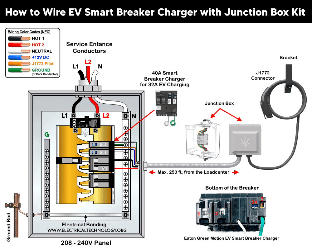
Step 2 – Install Conduit Between Panel and Junction Box
- Mount the junction box at the desired charging location.
- Install conduit between the loadcenter and junction box.
- Pull all required conductors through the conduit.
- Follow conductor sizing requirements based on distance.
Note: For underground installations, the J1772 pilot conductor should be RG6 Quad Shield cable and the shield must be grounded at the distribution panel.
Step 3 – Mount and Prepare the Junction Box
- Open the junction box cover.
- Secure the enclosure to the wall.
- Remove required ¾-inch knockouts.
- Install NM/SE connectors.
- Route:
- Field-installed conductors from the panel.
- EV connector cord into the junction box.
Step 4 – Terminate EV Connector Conductors
Connect the EV connector conductors to the color-coded terminal blocks in the junction box:
| Terminal Block | Wire Color | Function |
| Red | Red | Line 1 |
| Black | Black | Line 2 |
| Blue | Blue | +12 VDC |
| Orange | Orange | J1772 Pilot |
| Green | Green | Ground |
Strip conductors approximately 10 mm (0.39 inch). Tighten terminal screws to 13.3-15.9 in-lb (1.5-1.8 Nm).
Step 5 – Connect Junction Box Conductors to Charger
At the loadcenter:
- Install two NM/SE connectors.
- Route conductors into the loadcenter.
- Terminate conductors to the EV Smart Breaker Charger terminals:
- Terminal 1 to Line 1
- Terminal 2 to Line 2
- Terminal 3 to +12 VDC
- Terminal 4 to J1772 Pilot
- Terminal 5 to Ground
- Tighten all terminations securely.
Good to Know: There are two types of conductors in the cord i.e. High-voltage conductors e.g. Line 1, Line 2, Equipment ground and low-voltage conductors e.g. +12VDC and J1772 Pilot.
These conductors may share the same conduit only when all insulated conductors are rated for at least 250V. Otherwise, separate conduits must be used.
Step 6 – Install Cord Management Bracket
- Drill 1/8-inch (width) and 5/8 inches (depth) hole at both of the hole locations.
- Mount the bracket near the charging location.
- Secure using four #10 × 1½-inch screws.
- Install on a stud-backed wall whenever possible.
- Position so the charging cord can be wrapped neatly around the bracket.
Step 7 – Energize and Test
- Reinstall all covers and restore power.
- Verify BlinkUp and charger LEDs illuminate.
- Place breaker handle in ON position.
- Connect a vehicle and confirm charging operation.
Configuration and Wi-Fi Network Setting
When the EV Smart Breaker Charger has been successfully installed, restore power at the main service panel. The next step is to configure the charger using the mobile app.
To remotely control and monitor the EV Smart Breaker Charger over a Wi-Fi network, download the Eaton Brightlayer Home app from the Apple App Store (iOS) or Google Play Store (Android). The app provides convenient home energy management and EV charging control.
Using the app, you can remotely start, stop, monitor, and manage charging sessions from anywhere. It also provides real-time charging statistics, energy consumption data, and charging insights. In addition, you can schedule charging sessions based on Time-of-Use (TOU) utility rates to help reduce overall charging costs.
The app can send notifications for power outages, ground-fault events, charging status updates, and other charger-related alerts. You can also set a charging limit and adjust the charging current, with a minimum charging rate of 6A.
To commission and configure the EV Smart Breaker Charger for your preferred charge-management solution, download the EM Install app.
For Wi-Fi setup, app pairing, and advanced smart-control features, follow the step-by-step instructions in the guides below:
- Connect Eaton’s EV Smart Breaker Charger to the EV Charger Manager app.
- Connect Eaton’s EV Smart Breaker Charger to Charging Network Manager using the EM Install app.
- Connect Eaton’s EV Smart Breaker Charger to the Brightlayer Home app.
Warning
- Make sure to disconnect the power supply by switching OFF the breaker in the main panel before doing any electrical work.
- If you are unsure, contact a licensed electrician to do it according to the local area codes.
Disclaimer:
The author will not be liable for any losses, injuries, or damages from the display or use of this information or if you try any circuit in wrong format. So please! Be careful because it’s all about electricity and electricity is too dangerous. If you are unsure, contact a licensed electrician to do it according to the local area codes.
Resources:
EV Charger Wiring Series
- How to Wire an EV Wall Charger – Hardwired and Plug-in
- How to Wire ChargePoint Home Flex Charger for Every EV
- How to Wire Smart Electric Vehicle Charging Station – 32A/80A
- How to Wire 48A Level 2 Dual Port EV Charging Station
- How to Wire and Use Tesla Gen 3 Mobile Connector Charger
- How to Wire a Tesla Wall Connector & Universal EV Charger
Smart Devices Wiring Series
- How to Wire a Smart Switch in a 120/240V Load Center
- How to Wire 120/240V Smart Load Center with Smart Breakers
- How to Wire a Smart Breaker in a Smart 120/240V Panel
- How to Wire a Smart GFCI Breaker in a 120/240V Smart Panel
- How to Wire Smart AFCI/GFCI Breaker in a Smart Load Center
- How to Wire a 15A Wi-Fi Smart Outlet in a Smart Panel
- How to Wire 15A and 20A Wi-Fi Smart GFCI Outlets
- How to Wire Z-Wave Smart Switch, Dimmer & Fan Speed Controller
- How to Wire a Digital and Wi-Fi Smart LED Dimmer Switch
- How to Wire a Smart Switch Companion with a Smart Switch
- Wiring a Smart Dimmer Switch Companion with a Digital Dimmer
- How to Install a Wire-Free Smart Dimmer Anywhere Companion
- How to Wire Smart Scene Controller Switch
- How to Install a Wireless Smart Scene Switch
- How to Install a Wake and Sleep Wireless Smart Switch
- How to Wire a Smart Motion Sensing Dimmer Switch
- How to Wire a Combo Humidity Sensor & Fan Control with Light Switch
- How to Wire Humidity Sensor and Fan Control Switch
- How to Wire a Countdown Timer Switch – 15 Mins to 12Hrs
Wiring Standard GFCI & Breakers
- How to Wire a 1-Pole Breaker
- How to Wire a 2-Pole Breaker
- How to Wire a 3-Pole Breaker
- How to Wire a 1-Pole GFCI
- How to Wire a 2-Pole GFCI
- How to Wire a 3-Phase, 3-Pole GFCI
- How to Wire a Tandem Breaker
- How to Wire GFCI Circuit Breakers
- How to Wire an AFCI Breaker
Main Panels Wiring Tutorials
- How to Wire 120V/240V Main Panel? Breaker Box Installation
- How to Wire 120/240V Smart Load Center with Smart Breakers
- How to Wire 208V/120V, 1-Phase & 3-Phase Main Panel?
- How to Wire 240V, 208V & 120V, 1 & 3-Phase, High Leg Delta Main Panel?
- How to Wire 277V/480V, 1-Phase & 3-Phase Main Service Panel?
- How to Wire a Subpanel? Main Lug Installation for 120V/240V
- Single Phase Electrical Wiring Installation in Home according to NEC & IEC
- Three Phase Electrical Wiring Installation in Home – NEC & IEC
- How To Wire a Single Phase kWh Meter – 120V/240V
- How to Wire a Three-Phase Meter? 120/208/240/277/347/480/600V
- How to Wire Spa Panel for Hot Tub using 2-P GFCI & Breaker
Wiring General Outlets & GFCI/AFCI Receptacles
- How to Wire an Outlet Receptacle? Socket Outlet Wiring Diagrams
- How to wire a GFCI Outlet?
- How to Wire an AFCI Outlet?
- How to a Wire 3-Way Combination Switch and Grounded Outlet?
- How to Wire a 15A – 125V Outlet – NEMA 5-15 Receptacle
- How to Wire a 20A – 125V Outlet – NEMA 5-20 Receptacle
- How to Wire a 15A – 250V Outlet – NEMA 6-15 Receptacle
- How to Wire a 20A – 250V Outlet – NEMA 6-20 Receptacle
- How to Wire a 30A – 250V, NEMA 6-30 Receptacle
- How to Wire a 50A – 125/250V Outlet – NEMA 14-50 Receptacle for EVs
Sizing Breakers, Wires & Panels
- How to Size a Load Center, Panelboards and Distribution Board?
- How to Determine the Right Size Capacity of a Subpanel?
- How to Find the Right Wire Size for 100A Service 120V/240V Panel?
- How to Size a Circuit Breaker?
- How to Find the Proper Size of Wire & Cable In Metric & Imperial Systems
- How to Size a Breaker and Wires in AWG with EGC for Load?
- How to Size Service-Entrance Conductors and Feeder Cables?
- How to Size Feeder Conductors with Overcurrent Protection
- How to Size a Branch Circuit Conductors with Protection?
- How to Size Equipment Grounding Conductor (EGC)?
- How to Size Grounding Electrode Conductor (GEC)?
- How to Size Main Bonding Jumper (MBJ)?
- How to Size Motors FLC, HP, Voltage, Breaker Size and Wire Size
- What is the Correct Wire Size for 100A Breaker and Load?
- What is the Right Wire Size for 15A Breaker and Outlet?
- What is the Suitable Wire Size for 20A Breaker and Outlet?
-
 BYD Orders 10 More Ships to Carry 130,000+ EVs Worldwide
-
 BYD Launches Electric Truck to Rival Tesla Semi in Europe
-
 BYD’s New Electric Truck for EU Beats Tesla Semi in Almost Every Metric
-
 Windrose Electric Trucks Enter Australia’s Long-Haul Freight
-
 Germany’s Electric Drone Hits 699 km/h, Eyes World Record
-
 How to Wire and Use Tesla Gen 3 Mobile Connector Charger