Three-Speed, One-Directions, 3-Phase Motor (Multispeed) – Power & Control
How to Control a 3-Phase Motor for 3-Speed and 1-Direction using Dahlander Connection?
In applications where multi-speed control and one-direction rotation are needed, a specialized configuration utilizing both Dahlander connection and an additional winding can be employed. The supplementary winding is used for low speed while the other winding in Dahlander connection to achieve a three-speed control. In this article, we will show how to control a pole-changing three-phase induction motor having two separate windings for three different speeds and one direction of rotation with the help of power and control wiring diagrams?
Related Posts:
- Two-Speed, One-Directions, 3-phase Motor – Power & Control Diagrams
- Two-Speed, Two-Directions, 3-Phase Motor – Power & Control Diagrams
Components Needed
- Three-Phase Dual / Tap-Wound Motor
- 4 Nos. of Contactor
- 3 Nos. of Thermal Overload Relays
- 3-P MCCB
- 2-P MCB
- 4 Nos. of pushbuttons
- Single-Phase & Three Phase Supply
- Wires & Cables
Wiring & Control of Dual/Tap Wound Motor for 3-Speed,1-Directions
- The K1 contactor is used for Low speed.
- The K2 contactor is used for Medium speed.
- The K3 contactor is used for Star connection.
- The K4 contactor is used for High speed.
Power Diagram of Dual/Tapped Changed Motor

Power Diagram of Dahlander Connection & Supplementary Winding

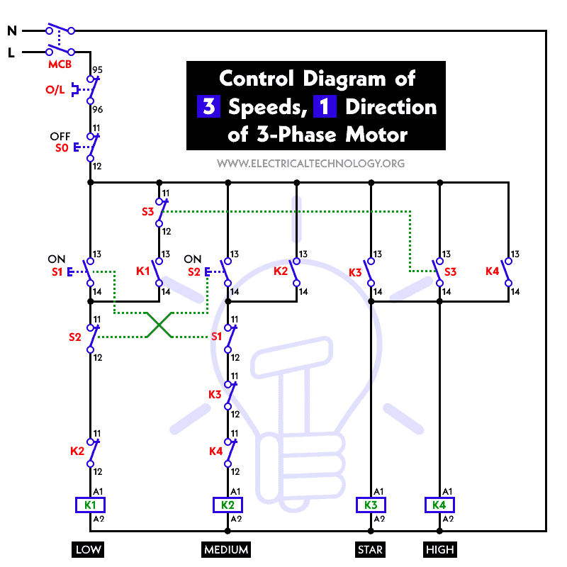
Control Circuit Diagram
Working & Operation of Multi-Speed Motor
Low Speed:
- When the operator presses the start pushbutton, the normally open contacts (NO) of S1 change their state from open to closed, i.e., they become normally closed (NC), which energizes the contactor K1.
- This process initiates to start and run the motor at low speed.
Medium Speed:
- When the operator uses the changeover switch (or a timer), the normally closed contacts of S2 change from closed to open, de-energizing the contactor K1.
- As the NO contacts of S2 change their state from NO to NC, contactor K2 energizes.
- This action is only possible when the normally closed contacts of K1 are opened due to interlocking.
- When contactor K2 is energized, it leads to run the motor at intermediate (medium) speed.
High Speed:
- When the normally opened contacts (NO) of S3 change their state from NO to NC, contactor K3 energizes.
- This is achievable only when the normally closed contacts of K2 close (thanks to the interlocking mechanism).
- This leads to the closing of the open contacts of K3.
- As a result, the line contactor K4 energizes, and the motor runs at high speed.
When the operator presses the OFF pushbutton S0, its NC contacts become open and all the contactors are de-energized, causing the motor to stop.
Unlike the Dahlander connection, which involves changing winding connections, the low-speed winding remains independent and is engaged when needed.
Related Posts:
- Star-Delta (Y-Δ) 3-phase Motor Starting Method by Automatic star-delta starter with Timer.
- Three Phase Motor Connection STAR/DELTA Without Timer – Power & Control Diagrams
- Three Phase Motor Connection Star/Delta (Y-Δ) Reverse / Forward with – Timer Power & Control Diagram
- Starting & Stopping of 3-Phase Motor from more than One Place Power & Control diagrams
- Control 3-Phase Motor from more than Two buttons – Power & Control Diagrams
- ON / OFF Three-Phase Motor Connection Power & Control Schematic and Wiring Diagrams
- Three Phase Motor Connection Reverse and Forward – Power and Control wiring diagrams
- Three Phase Slip Ring Rotor Starter – Control & Power Diagrams
- Even Motor Power & Control Circuit Diagrams for 3-Phase Motor


Naji Sajed <br />like it <br />
interrestin site
i like your website