High Inrush Current in Capacitor Switching and Ways to Prevent It.
How to Prevent the high Inrush Current in Capacitor Switching?
Introduction to High Inrush Current in Capacitor Switching
Applications of capacitance switching are not only restricted to capacitive currents but they have their implementation in energizing process of capacitors banks, overhead lines and cables. Capacitors banks switching are known to be cause of very large value of transient voltage across the contacts of circuit breaker.
The capacitive switching characterized by commonly, switching of low to mode rate currents in industrial or public networks, and by a low rate of rise of recovery voltage. New circuit breakers (CBs) which argue a long mechanical and electrical life without maintenance seem to be best adapted to this switching duty recently developed SF6 puffer has been designed for better performance with less interrupter per pole but obviously an ideal scenario cannot be attained. In power system circuits where circuit breaker have wide applications to prevent damage ,imbalance of voltages along the terminals of circuit breaker can lead to high inrush current that’s why any interruption in capacitive current can cause issues in dielectric used for switching of devices. Capacitors in capacitors bank can get damaged due to heavy inrush current.
In power system many lumped capacitors bank are present to regulate voltage, to improve the PF (power factor) and also capacitor banks have a lot of application in filtration of high harmonics in the overall system.
In distribution process of power system there are cable networks that generates capacitive load. When any current interruption occur in the system capacitive load get charged and this charge in capacitors expose the circuit to get damaged by re-ignition of dielectric along with generating high over-voltage .
When large inrush current start flowing through substations ,the system is imposed to face consequences that occur in protection system and also while switching when voltage present in line start oscillating at slightly low frequency then its magnitude become equal to double of the peak voltage present in the circuit that can cause severe hazards. In this article it will be discussed that how we can minimize the high inrush current and what are the basic recommendations for it
Methods To Insert capacitors in order to prevent inrush current
There are two ways to place capacitors in such a way that inrush can be minimized to negligible. Both these methods are described here one by one.
A single Capacitor Bank Circuit
First Scenario
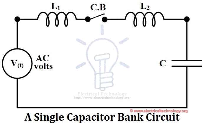
Let’s consider the circuit above it is one phase circuit and has lumped elements for a capacitive circuit. It has a circuit breaker which close its contacts in any interruption ,one capacitor and two inductors present in the circuit assuming that resistance of the circuit is approximately is zero and value of inductor L1 is greater than L2.
A circuit breaker is present in the circuit to define the interruption in the circuit. This circuit form is called isolated bank of capacitor.
In this case current depends on the circuit parameters and initial state of the circuit. Suppose that capacitor is charge to voltage v0 at time t0. Current can be calculated from expression;
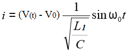
Where: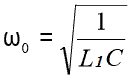
In this scenario due to damping current will decrease and overall current in the circuit will be established.
A back-to-back Capacitor Bank Circuit
Second Scenario:
This scenario is known as bank to bank capacitive switching let’s consider the diagram for it.

In this case there are two capacitors and two inductors when circuit breaker is closed in interruption if their occur any dielectric breakdown at point b-b’ (i.e. difference in voltage at two contacts of circuit breaker) then expression of current can be computed as
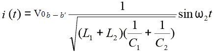 Where:
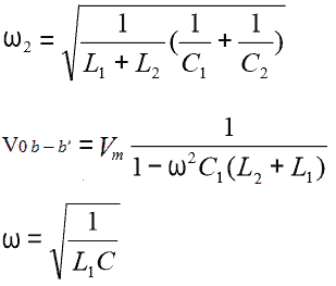
In this current can be around ten times more than the peak current present in the circuit but this current can effect only one capacitor (local) and rest of the system will be safe.
Steps to Prevent High Inrush Current
Here are some recommendations to get rid of this high inrush current.
- There must be a resistor present in the circuit as resistance will increase current will be utilized to some level.
- Extra reactance can be placed in the system because by placement of extra reactance there will be extra energy losses in the system along with reduction in effects of capacitors.
Synchronous Switching
As we know that high over voltage is created by breakdown of dielectric between the contacts of circuit breaker, we have to remove this issue permanently . So in order to do remove issue of high over voltage it has to be made sure that when in any interruption situation a circuit breaker is closed there should be no voltage difference between the contacts of CB.
One cannot attain the ideal situation as factor of plus and minus is always there so synchronous switching is one of solution. So a device has been manufactured by the name of SmartClose Capacitor switch which can convert any bank to synchronous bank by using sensors.
Features and Working of SmartClose Switch.
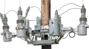
It has 6 voltage sensors that detect the voltage waveform on both the capacitor side and the source side of each interrupter. A close has been command issued by a separate capacitor bank controller causes the SmartClose capacitor switch to close each interrupter independently when the voltage difference across each interrupter is zero, then close command is issued to the SC (SmartClose)will kick off zero voltage closing in all circuit.
The separate controller of each capacitor bank decides when the capacitor bank is needed; the SmartClose switch grasps that and does the whole thing by synchronous close automatically.


Great article!
Love the part about Synchronous Switching, no one ever seems to know enough about this!
Thanks for sharing!
How can i make cooler by using bottles chargers ice cubes.