What is Raspberry Pi? Creating Projects using Raspberry Pi
What is Raspberry Pi?
Using Raspberry Pi to control LEDs (Simple Electronic Project)
What is Raspberry Pi?
Raspberry Pi is a small credit card sized microcomputer consisting of inbuilt features like SD card slot, wireless LAN and Bluetooth and 1.2GHZ ARM processor etc (More components details are given below). It can be used by enthusiasts to build small practical projects. It was first developed by Raspberry Pi Foundation in 2012. lets discuss the Raspberry in details and try to make a simple electronic project with it (Step by step tutorial with code).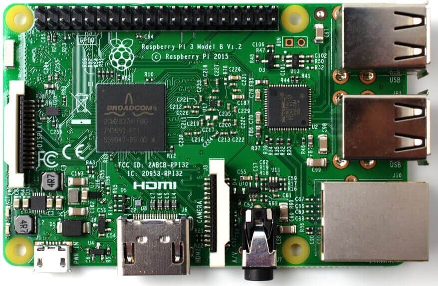
- Also Read: What is ZigBee Technology and How it works?
Construction of Raspberry Pi
Following components are available in a Raspberry Pi board
- General Purpose Input/output Pins for connection to external hardware and other electronics project.
- A micro USB port to insert a USB cable for powering.
- USB Ports for connection with keyboards, Mouse, Webcams etc.
- A micro SD card slot to insert a SD card, to load the operating system ‘Raspbian’.
- A HDMI socket for connection with a computer monitor or a television.
Different versions include Raspberry Pi Model A, Raspberry Pi Model B, Raspberry Pi Model B+, Raspberry Pi Model B+ Version2 and the Raspberry Pi3 ( The latest version supporting 1.2GHz ARM CPU, Bluetooth 4.1, Wi-Fi, 1 GB RAM etc).
Basic circuit components and parts of Raspberry Pi 3 Model B
Click image to enlarge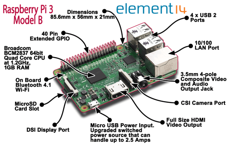
Fig – Raspberry Pi 3 Model B
Difference between Raspberry Pi B and Raspberry Pi B+
Click image to enlarge

Fig: Difference between Raspberry Pi B and Raspberry Pi B+
Creating Projects using Raspberry Pi
Essential elements for beginners, to create a project using Raspberry Pi, are a keyboard, mouse, operating system, a smart phone charger, a display and a HDMI cable.
The SD card acts as a hard drive and can be used to install the operating system to store all the documents, code etc. Popular brands are Samsung Evo and SanDisk Extreme.
The first task involves loading the operating system onto the SD card. Though officially ‘Raspbian’ operating system is used, other operating systems like Windows 10 IoT core and Ubuntu Mate can also be used.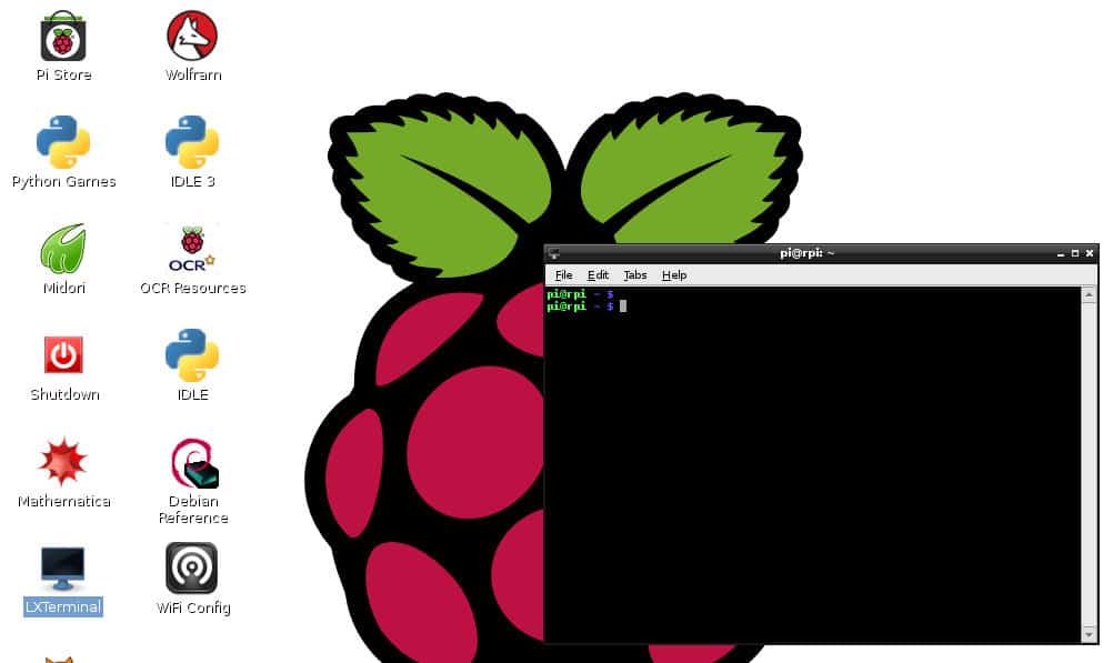
Raspbian is a Linux based, open source operating system, allowing user to view and modify the source code. It can be either installed using New Out of Box Software (NOOBS) approach or copy an image file of the whole operating system directly onto the SD card.
The SD card is first connected to Windows (or other OS) through a card reader or adapter. The card is then formatted using SD Card Formatter (using Windows FAT32 formatter).
The NOOBS file is next downloaded from the site: magpi.cc/2bnf5XF. The files are extracted from the downloaded zip folder and are copied to the roots of the SD card. Once the NOOBS is copied to the SD card, the latter is ejected from the computer and re-slotted to the Raspberry Pi board.
The board is then connected to the monitor through a HDMI cable, powered up using USB adapter, and connected to external peripherals like keyboard and mouse. Once powered up, the board will boot itself and display the NOOBS installer. The Operating System will be installed once the user confirms the same.
Once installed, the Raspbian operating system consists of Lightweight X11 Desktop Environment (LXDE) which enables a user to use the Raspberry Pi same as the computer. It consists of a Menu button, which enables access to several programs and apps. It supports web browser called ‘Epiphany’ and an email program called ‘Claws Mail’. It can be connected to internet using Ethernet or Wi-Fi.
The settings can be adjusted either using the desktop interface or a terminal program called ‘Raspi Config’. Similar to Microsoft Office in Windows, the Raspbian operating system consists of LibreOffice system with programs like Writer (Word), Calc (Excel Spreadsheets), Impress (Presentations), Draw (Vector Graphics and Flowcharts), Base (Database) and Math (Formula Editing).
General Purpose Input/Output Pins
The Raspberry Pi consists of 40 General-Purpose Input/Output Pins (right one in the fig below) which acts as interface between the board and external electronic components (LEDs, Relays, Motors etc) or projects (Arduino). These components need to be connected to the GPIO pins and are controlled using corresponding Python programming.
The GPIO pins also enable connection to Sensors and other peripherals through different communication techniques like I2C (Inter-Integrated Circuit), SPI (Serial Peripheral Interface) and UART (Universal Asynchronous Receiver Transmitter).
Click image to enlarge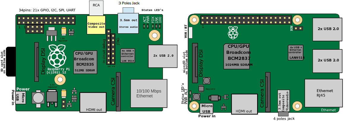
Fig – Basic Components Diagram of Raspberry Pi
- You May Also Read: Fully Automatic Water Level Controller using SRF04
These pins also allow connection to in-built Hardware attachments (known as Hardware Attached on Top), which work as soon as they are connected to Raspberry Pi.
However, it should be noted that randomly connecting GPIO pins to high power devices, like Motors, would be unsafe on a breadboard and a better option is to use a ‘Breakout’ cable between a Breadboard and the Pi board.
These pins generally act as Input or Output pins. While acting as Output pins they can either have HIGH or LOW states, as Input pins they can either be pull-up or pull-down connections.
Programming using Raspberry Pi
The primary programming language used with Raspberry Pi is Python, a dynamic programming language used in variety of applications and similar to TCL, Pearl, Ruby or Java. The syntax is simple and uses standard English keywords.
A Python program can be written using IDLE, a development environment. It provides a Read-Evaluate-Print-Loop (REPL) prompt to enter Python commands. It can also be written using Leafpad Text editor.
Using Raspberry Pi to control LEDs (Simple Electronic Project)

Step 1: The first step involves the hardware connection, i.e. connecting the cathode of both LEDs to two GPIO pins and the push button switch to another GPIO pin.
Step2: Next step involves importing the library files and writing the code
In the linux command terminal, write the below code
Sudo apt-get install RPi.GPIO.
Step 3: Next step is opening the IDLE program and write the below code
Import Rpi.GPIO as GPIO
Import time
GPIO.setmode (GPIO.BCM)
Green_LED = 17
Red_LED = 27
Button = 18
GPIO.cleanup ()
GPIO.setup (Green_LED, GPIO.output)
GPIO.setup (Red_LED, GPIO.output)
GPIO.setup (Button, GPIO.IN, pull_up_down = GPIO.PUD_DOWN)
Input_state = GPIO.input (Button)
If Input_state = = True:
Print (‘Green LED On’)
GPIO.output (Green_LED, GPIO.HIGH)
time.sleep (0.2)
Else
Print (‘Red LED On’)
GPIO.output (Red_LED, GPIO.LOW)
time.sleep (0.2)
Let us have a brief discussion about the above code.
1. The first two lines of the codes import the necessary library files and the timer related file.
2. The third line represents assigning the GPIO pin numbering. Note that there can be two modes to do the same – using the Broadcom SoC numbering (BCM) or BOARD mode. While the latter uses the same numbering sequence as the board, the former uses different ways.
3. The next three lines represent giving different names to the GPIO pins to be used.
4. The 7th Line involves calling the cleanup () function to make sure all the input/output channels are free to use.
5. The next two lines involve setting up of the LED connected pins as output pins.
6. The next line involves setting up of Push Button connected pin as input pin. Notice the argument ‘pull_up_down = GPIO.PUD_DOWN). As mentioned above, GPIO pins can be used as input through either pull up or pull down connection.
Reason is, each GPIO has software configurable resistors which can be used in pull up or pull down mode. Omitting this argument in the function would keep the input pin floating. So, the written command would enable the pull down resistor and once the Push Button is pressed, ‘True’ will be returned.
7. In the next set of lines, controlling of LEDs is mentioned, wherein once the Push Button is pressed, Green LED will be On and when not pressed, Red LED will be On.
Notice that unlike in other programming languages like C, Java, we have not used parenthesis or brackets to differentiate loops, instead here indentation is used.
Step 4: The next step involves saving the file and pressing ‘Run’ or ‘F5’ to run the code.
This is a small basic overview about Raspberry Pi. Though this board is similar in functionality to Arduino, yet Arduino is preferred for simpler projects compared to Raspberry Pi. The reason, readers are welcome to mention in the below section.
You may also read:


We recently launched an IO card for Raspberry Pi targeting Industrial Automation with the following resources:
Four each, 0-10V inputs and outputs
Four each, 4-20mA inputs and outputs
Four optically isolated digital inputs
Four optically isolated open drain outputs with PWM
Four optically isolated, 10A/250V relays
MODBUS, CAN and 1-Wire communication ports
RTC with super-cap backup
Command Line. Python and CODESYS drivers can be downloaded from GitHub.
All channels are calibrated to better than 0.2% linearity.
Up to four cards can be stacked on top of one Raspberry Pi
I am trying to operate servo motors with a raspberry pi using a cell phone for internet access and was trying to operate from my home computer with integrated vision