Digital Synchronous Counter – Types, Working & Applications
Digital Synchronous Counter – Types & Applications
What is Digital Counter?
A digital binary counter is a device used for counting binary numbers. Digital counters mainly use flip-flops and some combinational circuits for special features.
As we know flip-flop operates on clock pulses. So the counter will count up or down using these pulses. The time period of clock signal will affect time delay in the counter. So this counter can also be modified into a timepiece given the clock signal has a time period of 1 second.
What is Synchronous Counter?
As the name implies, the synchronous counter contains flip-flops which are all in sync with each other i.e. their clock inputs are connected together and are triggered by the same external clock signal. This implies that all the flip-flops update its value at the same time.
Types of Synchronous Counters
There are two types of counters.
Synchronous counters and Asynchronous Counters. The synchronous counter has many types. Some of them are given below.
- Up-Counter
- Down Counter
- Up/Down Counter
- BCD Counter
Up Counter
This synchronous counter counts up from 0 to 15 (4-bit counter). Up counter can be designed using T-flip flop (JK-flip flop with common input) & D-flip flop. Both of these flip-flops have a different configuration.
Consider a 3-bit counter with each bit count represented by Q0, Q1, Q2as the outputs of Flip-flops FF0, FF1, FF2 respectively.Then the state table would be:
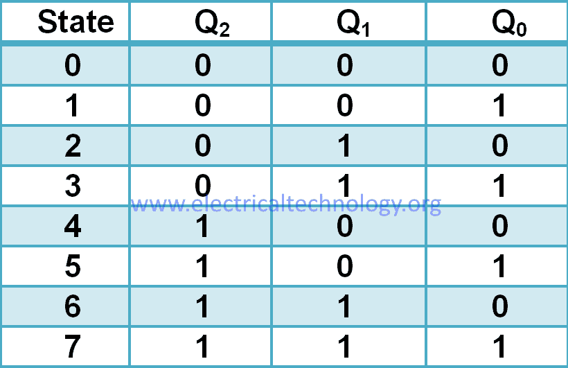
The counter is a memory device. It means it has previous & next states.
Design Using T-Flip Flop
T-Flip flop toggles it state when input = 1 and holds its state when input= 0.
According to the state table of up-counter
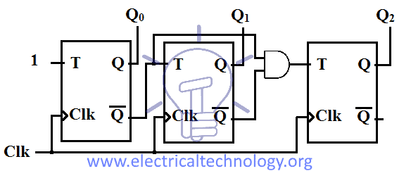
Q0 is continuously toggling so the input to the FF0 will be permanent 1. i.e. T0 = 1.
Q1 toggles its state when the previous state is Q0 = 1. So the input to FF1 will be the output of FF0 i.e. T1 = Q0
Q2 toggles when both Q0 & Q1 are 1. So the input to FF2 will be the AND of outputs of FF0 & FF1 i.e. T2 = Q0 & Q1.
The schematic for Up-counter using T-flip flops is given below.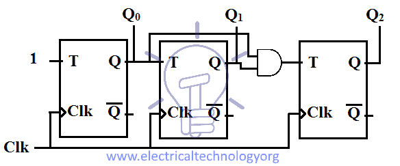
Design Using D-Flip Flop
D-Flip flop updates its state according to the input applied to it i.e. Q = D. So designing up-counter using D-flip flop is different than a T-flip flop.
According to the state table of up-counter
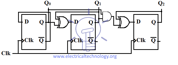
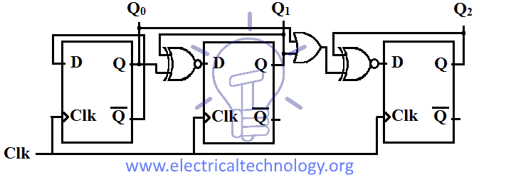
Q0 is continuously changing so the input to FF0 will be D0 = Q̅0. Because it will toggle the state whenever a clock pulse hits the FF0.
Q1 = 1, when its previous state Q1 &Q0 are not equal & Q1 = 0, when its previous state Q1 &Q0 are equal. That is the same as XOR operation. So D1 = Q1 XOR Q0.
Q2 = 1, when in its previous state the AND of Q1 & Q0 is not equal to Q2. Q2 = 0, when in its previous state the AND of Q1 & Q0 is equal to Q2.So D2 = Q2 XNOR (Q1& Q0)
Schematic of Synchronous Up-counter using D-flip flop is given in the figure below.
- You may also read: Ring counter and Johnson counter
Down Counter
Down counter counts in descending order from 15 to 0 (4-bit counter). Down counter can also be designed using T-flip flop and D-flip flop.
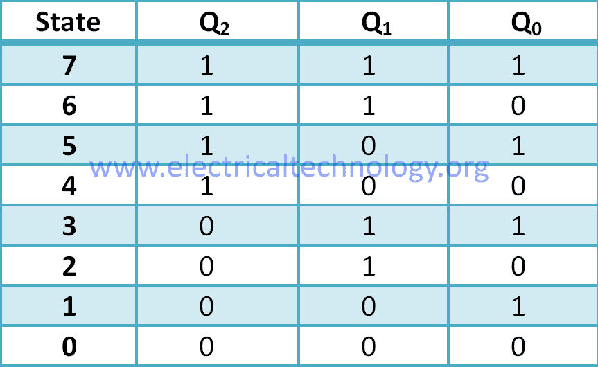
Consider 3-bit counter with each bit represented by Q0, Q1, Q2as the outputs of flip-flops FF0, FF1, FF2 respectively. The state table for down counter is given below:
Design Using T-Flip Flop
T-flip flop toggles its state when T-input = 1 & hold its state when T=0.
According to the state table of Down-counter
Q0 is continuously toggling so the input to the FF0 will be permanent 1. i.e. T0 = 1.
Q1 toggles its state when the previous state is Q0 = 0. So the input to FF1 will be the complemented output of FF0 i.e. T1 = Q̅0
Q2 toggles when both Q0 & Q1 are 0. So the input to FF2 will be the AND of complemented outputs of FF0 & FF1 i.e. T2 = Q̅0 & Q̅1.
The schematic for Down-counter using T-flip flops is given below
Design Using D-Flip Flop
D-flip flop updates its states according to the input D i.e. Q = D. so its design is different than T-flip flop design.
According to the state table of down-counter
Q0 is continuously changing so the input to FF0 will be D0 = Q̅0. Because it will toggle the state whenever a clock pulse hits the FF0.
Q1 = 1, when its previous state Q1 &Q0 are equal & Q1 = 0, when its previous state Q1 &Q0 are not equal. That is the same as XNOR operation. So D1 = Q1 XNOR Q0.
Q2 = 1, when in its previous state the OR of Q1 & Q0 is equal to Q2. Q2 = 0, when in its previous state the OR of Q1 & Q0 is equal to Q2.So D2 = Q2 XNOR (Q1 + Q0)
Schematic of Synchronous Down-counter using D-flip flops is given in the figure below.
Up/Down Counter
This counter has two modes of counting i.e. up counting and down counting. There is a mode switch which switches between the two modes of the counter. When the mode M = 0 it counts up & when mode M = 1 then it counts down.
This Counter combines up-counter & down-counter using 2_1 mux. The Mux selects one counter using the select switch which is the mode switch.
Design Using T-Flip Flop

We combine up & down counter of T-flip flop into one counter. We used 2_1 Mux for the inputs on each flip-flop except the first one.
When Mode = 0, the upper input will be selected and Up counting will start.
When Mode = 1, the lower input will be selected and down counting will start.
Design using D-Flip Flop
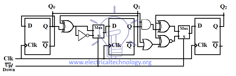
We use 2_1 Muxes to Combining Up & down counter using D-Flip flop into a single counter. The inputs to each flip-flop are selected by 2_1 Mux which selects the mode of the counting.
BCD Counter
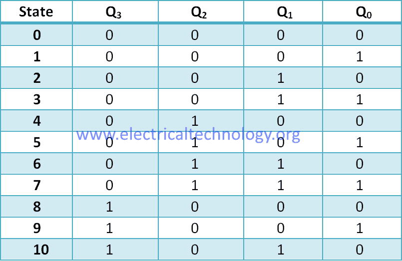
Binary coded decimal (BCD) counter is a modified binary counter with MOD n = 10. MOD is the number of states that a counter can have. Any counter with MOD = 10 is known as decade counter. It has 10 states each representing one of 10 decimal numbers. Which is why it is known as BCD counter. It counts from 0 to 9 and then it resets back to 0.
The default state of BCD counter is 0000 when it reaches decimal count 10 it resets to 0.
Consider Q0, Q1, Q2, Q3as 4 bits of the counter than the state table will be.
BCD counter can be made using T-Flip flop or D-Flip flop.
Design using T-Flip Flop
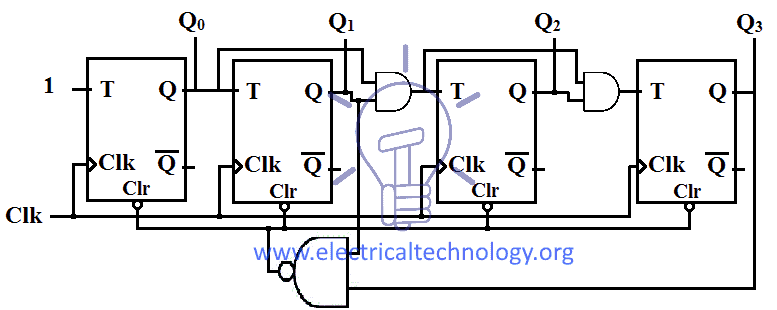
The designing of BCD counter using T-flip flop is same as Up-counter but there is a condition when the count or state reaches to 1010 (decimal 10) it will clear all the flip-flops to default state 0000 (decimal 0).
Flip flops normally have active low clear. So we have to apply combinational circuit to automatically reset the circuit upon reaching 1010 state. The combinational circuit should produce ‘0’ to clear the flip-flops.
NAND gate produces logic 0 when all its inputs are true so whenever Q3 & Q1 = 1, NAND will produce 0. Thus
Clear = (Q3& Q1)’
Schematic of BCD counter using T-flip flops is given below:
Design Using D-Flip Flop
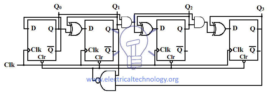
BCD counter using D-flip flop is a modified D-flip flop’s Up-counter. The modification it needs is the auto-reset function upon reaching the state 1010 which is decimal 10.
Reset function will clear the flip-flop to default state 0000 to start the count again from 0.
The combinational circuit for reset function is the same as in T-flip flop BCD counter.
Schematic of BCD counter using D-flip flop is given below.
BCD counters are used in digital clock and event counting.
Advantages / Disadvantages of Synchronous Counters
- Very easy to design this circuit because we may set the same clock pulse for all gates.
- Less likely to end up in erroneous states.
- They are faster as the the propagation delay are small as compared to asynchronous counters.
- There are no counting errors as compared to asynchronous counters.
- Performance is much better, liable and portable circuit.
Applications of Synchronous Counters
As the name suggest, Synchronous counters perform “counting” such as time and electronic pulses (external source like infrared light). They are widely used in lots of other designs as well such as processors, calculators, real time clock etc. Some common uses and application of synchronous counters are follow:
- Alarm Clock, Set AC Timer, Set time in camera to take the picture, flashing light indicator in automobiles, car parking control etc.
- Counting the time allotted for special process or event by the scheduler.
- The UP/DOWN counter can be used as a self-reversing counter.
- It is also used as clock divider circuit.
- The parallel load feature can be used to preset the counter for some initial count.
- Commons used in home appliances like washing machine, microwave own, Time schedule led indicator, key board controller etc.
- They are also used in machine moving control.
- Mostly used in digital clocks and multiplexing circuits.
- They are used to generate saw-tooth waveform (Stair case voltage)
- It is also used in digital to analog converters.
You may also read:


Hello,
In Synchronous Counter using D Flip-Flop. The diagram of UP counter and Down Counter need to exchanged.
UP Asyn using D FF should be in down and vice verse
Thanks,
Ramya