Types of Digital Logic Gates – Boolean Logic Truth Tables & Applications
Boolean Logic & Types of Basic Logic Gates? Symbols, Truth Table & Applications
What Is Boolean Logic?
Boolean logic refers to the form of algebra where the variables have only 2 unique values i.e. TRUE or FALSE or ON and OFF. These values are often used as 1 or 0 in binary language or High and low logic respectively.
| 1 | 0 |
| True | False |
| High | Low |
| ON | OFF |
Boolean Function
A Boolean function is a logical operation of one or more than one variables whose resultant is a single binary bit. It can only be either TRUE or FALSE. Boolean functions are based on Boolean logic.
What is a Digital Logic Gate?
A digital logic gate is an electronic component which implements a Boolean function. these logic gates may have two or more than two binary inputs and provides a single binary output. Some of these basic logic gates are given below:
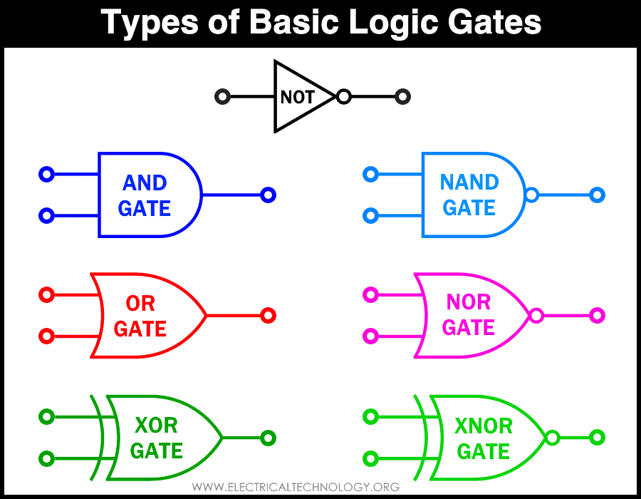
Types of Basic Logic Gates
Below are different types of basic digital logic gates with symbols and truth tables. You may find more details about each gate construction and working in links provide below the truth tables for each gate.
NOT Gate
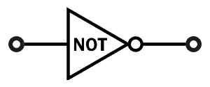
NOT gate is a basic digital logic gate. This logic gate inverts its input logic i.e LOW into HIGH and HIGH into LOW. It is also known as logic Inverter & is also sometimes referred to as negation buffer. NOT gate is a single input single output gate.
The logical operator for NOT is ‘!’ and it inverts its operand’s value.
The Truth table for NOT gate is:
| TT Table for NOT Gate | |
| Input | Output |
| 1 | 0 |
| 0 | 1 |
- Read more about : Logic NOT Gate – Digital Inverter Logic Gate
AND Gate

This digital logic gate implements the logical AND function, which is the Boolean product of two or more than two variables. AND operation is also known as a logical conjunction. In other words, the output of AND gate is TRUE when all of its inputs are TRUE.
AND function’s operator, the logical conjunction is denoted by ‘Λ’ or ‘.’.
AND gate has a minimum of two inputs and a single output. The truth table for AND gate is:
| TT Table for AND Gate | ||
| Input 1 | Input 2 | Output |
| 0 | 0 | 0 |
| 0 | 1 | 0 |
| 1 | 0 | 0 |
| 1 | 1 | 1 |
- Read more about : Digital Logic AND Gate
OR Gate:
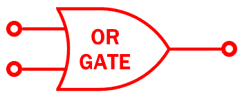
Digital logic OR Gate implements the logical OR function. Logical OR function gives TRUE output if any of its operands are TRUE. Thus, the output of OR gate is True if any of its Input is TRUE.
OR logic function is also known as inclusive disjunction. And its operator is ‘∨’ or ‘+’.
OR gate has a minimum of two inputs and a single output. The truth table for OR gate is:
| TT Table for OR Gate | ||
| Input 1 | Input 2 | Output |
| 0 | 0 | 0 |
| 0 | 1 | 1 |
| 1 | 0 | 1 |
| 1 | 1 | 1 |
- Read more about : Digital Logic OR Gate
NAND Gate:

NAND Gate is a digital logic gate which performs negative AND function. As its name suggests, NAND (NOT of AND) operation inverts the output of AND operation. In other words, the output of the NAND gate is Low only when all of its inputs are high.
NAND gate has a minimum of two inputs and a single output.
NAND gate’s truth table is
| TT Table for NAND Gate | ||
| Input 1 | Input 2 | Output |
| 0 | 0 | 1 |
| 0 | 1 | 1 |
| 1 | 0 | 1 |
| 1 | 1 | 0 |
- Read more about : Digital Logic NAND Gate – Universal Gate
NOR Gate:
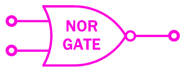
The digital NOR gate is a Negative-OR gate. The operation of NOR is negation or NOT of logical OR gate. In other words, the output of NOR gate is LOW when any of its input is HIGH and vice versa.
It has a minimum of two inputs and a single output.
The truth table of NOR gate is
| TT Table for NOR Gate | ||
| Input 1 | Input 2 | Output |
| 0 | 0 | 1 |
| 0 | 1 | 0 |
| 1 | 0 | 0 |
| 1 | 1 | 0 |
- Read more about : Digital Logic NOR Gate – Universal Gate
XOR GATE:
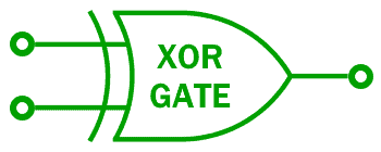
Exclusive-OR or XOR gate is a digital logic gate used as a parity checker. XOR gate provides output TRUE when the numbers of TRUE inputs are odd. For a two-input XOR gate, the output is TRUE if the inputs are different. Otherwise, the gate will produce FALSE output.
The truth table of XOR gate is following
| TT Table for XOR Gate | ||
| Input 1 | Input 2 | Output |
| 0 | 0 | 0 |
| 0 | 1 | 1 |
| 1 | 0 | 1 |
| 1 | 1 | 0 |
- Read more about : Exclusive-OR (XOR) Digital Logic Gate
XNOR GATE:
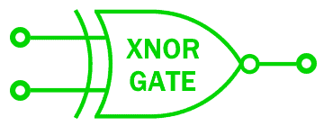
XNOR gate or Exclusive NOR gate is the negative or inverse of XOR gate. Generally, XNOR gate give output TRUE if it has EVEN number of TRUE inputs.
The output of two-input XNOR gate is TRUE if the inputs are same. When the inputs are different, the 2-input XNOR gate produces FALSE output.
The following is the Truth table for XNOR gate
| TT Table for XNOR Gate | ||
| Input 1 | Input 2 | Output |
| 0 | 0 | 1 |
| 0 | 1 | 0 |
| 1 | 0 | 0 |
| 1 | 1 | 1 |
- Read more about : Exclusive-NOR (XNOR) Digital Logic Gate
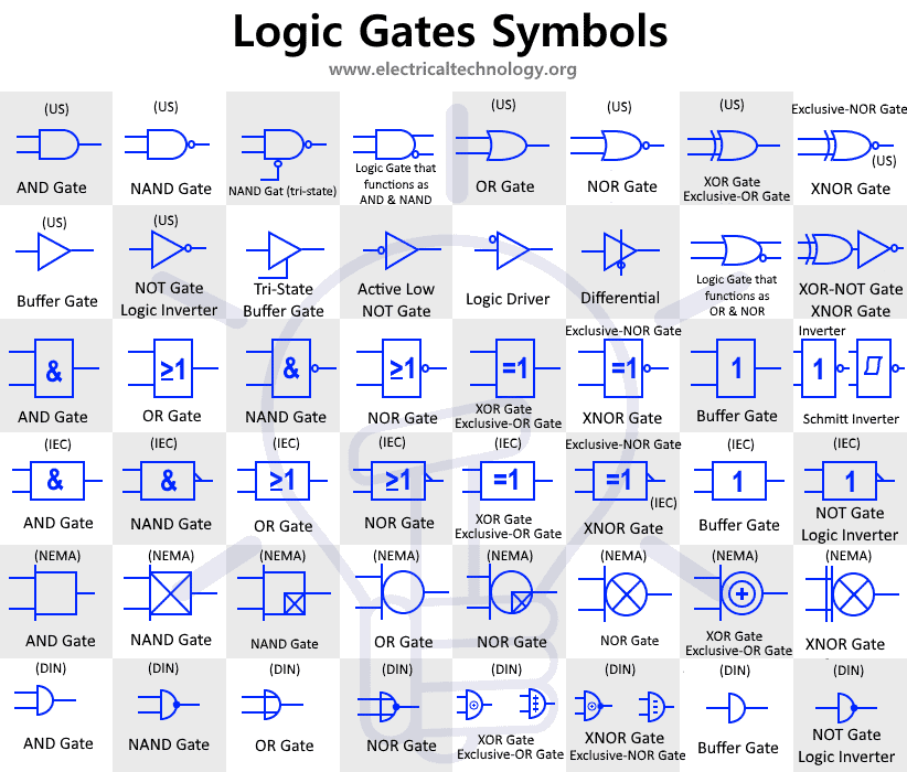
Logic Gates Symbols:
The post named as “Digital Logic Gates Symbols” has been published with different logic gates symbols with description and truth tables. The following table shows all the basic logic gates symbol in single image.
Applications Of Digital Logic Gates
The applications of logic gates are unlimited because its applications depend on its truth table where numerous combinations of logic gates combine together to form a specific logic circuit that either be combinational logic or sequential logic.
The logic gate combines together to form the ALU (Arithmetic Logic Unit) which can perform the arithmetic & logic operations. ALU is used in every digital computational system such as a calculator, computer, cell phone etc.
The logic gates are also the basic element for latches and flip-flops which constitutes a memory block. The memory block is used for storing data which is used in storing temporary data which is volatile such as in RAMs (Random Access Memory) or storing any permanent data such as memory sticks (thumb drives) etc. The digital counters are also made up of flip-flops & latches.
The Digital logic gates are the basic building block of any digital component, device or system. we will look into some of the common uses of logic gates in practical scenarios.
- The most common use one can think of is AND gate used as an ALARM. where one input is used as a switch ON/OFF while the other input is connected to any sensor. The ALARM can be modified to be used in various situations such as a smoke sensor being used in a smoke/fire ALARM, Person sensor in burglar Alarm etc.
- Another application of logic gate is Two-way switch using logic XOR gate. The output of XOR gate is triggered (turn ON/OFF) by triggering any of the two inputs without interfering the other. so the input switches in the stairway are connected with the inputs of the XOR & the output is connected to the light. In such way, the XOR gate operates as a digital two-way switch.
Related Posts:


Positive thinking leads to positive life, and negative thinking leads to negative life