Digital Logic Gates Symbols
Logic Gates Symbols
The following terms are used for basic Logic Gates symbols in the post. ANSI: It stands for American National Standards Institute DIN : It stands for Deutsches Institut für Normung’ which means ‘German Institute of Standardization IEC : It stands for International Electrotechnical Commission
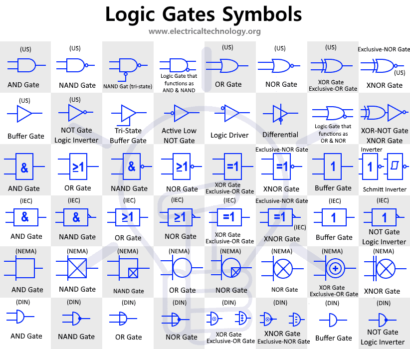
Digital Logic AND Gate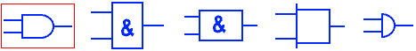
The AND Gate performs the logical (inclusive) conjunction (True output only if all True inputs). It provides output “HIGH” logic only when it’s all inputs are logic “HIGH”. And it provides logic “LOW” when one or all of the inputs are logic “LOW”.
Digital Logic OR Gate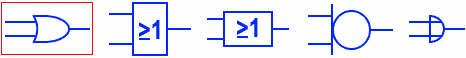
The OR Gate performs the logical (inclusive) disjunction (True output for any True input) The output of OR gate is logic “HIGH” when one or more than one of its inputs is logic “HIGH”. The output only remains logic “LOW” when all of its inputs are logic “LOW”.
Digital Logic NOT Gate
NOT gate, also known as logic Inverter, is a single input single output logic gate. It inverts the input logic. The output is logic “LOW” when the input is logic “HIGH” & the output is logic “HIGH” when the input is logic “LOW”.
Active Low NOT Gate![]()
The bubble before the gate shows that it is an active low logic gate. it has the same function as a common NOT gate.
Schmitt inverter:
The Schmitt inverter is a logic gate designed with the hysteresis phenomenon due to the positive feedback inside the gate. the main difference between generic inverter & Schmitt inverter is due to its threshold level. The former has fixed threshold that defines the LOW & HIGH Logic, the later has threshold level that resembles a BH hysteresis curve i.e. the threshold from Low to High & High to Low are different.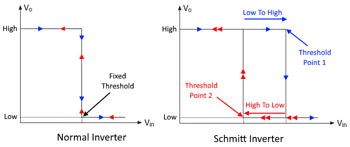
Digital Buffer Gate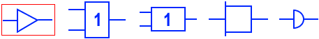
A Buffer gate has single input & single output. It does not change the input logic. It is mainly used to increase the signal propagation delay.
Digital Tri-State Buffer Gate![]()
Such type of Buffer gate has an extra control pin (also known as enable pin). It is used to control the flow of logic. If the control pin is HIGH the input logic flows out otherwise the output is “High Impedance State Z”
Digital Logic NAND Gate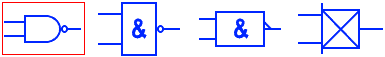
The NAND Gate is the Inverse of AND gate or “NOT of AND” gate. Its output is logic “High” when any of the input is logic “LOW” & its output is logic “LOW” when all of its inputs are logic “HIGH”.
Digital Logic NOR Gate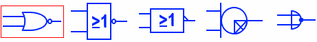
NOR Gate is Negative or inverse of OR gate or “NOT of OR” gate. It gives logic “HIGH” when all of its inputs are logic “LOW” & gives logic “LOW” when any of the inputs are logic “High”.
Digital Logic XOR Gate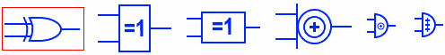
XOR Gate also known as Exclusive OR Gate, implements exclusive disjunction (Output true when only one input is true). The output of XOR gate is HIGH when only one input is HIGH otherwise the output is LOW.
Digital Logic XNOR Gate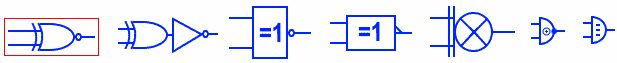
The XNOR Gate also known as Exclusive NOR Gate, is an invert of XOR gate. It implements the function of equality. The output is True only if the input’s logic are same i.e. the output is HIGH only when all the inputs are “HIGH” or “LOW”
IMPLY Gate![]()
The IMPLY logic gate implements a “logical conditional”. It forms the statement “If A then B”.
The output of this gate is, “if the input A is true then input B is also true” So when A is True “HIGH” and B is True “HIGH”, the output is true “HIGH”. When A is true but B is false then the output is false. Now if the input A is false then automatically the output becomes true regardless of input B i.e. the output is True in both cases.
| A | B | Output |
| 0 | 0 | 1 |
| 0 | 1 | 1 |
| 1 | 0 | 0 |
| 1 | 1 | 1 |
NIMPLY Gate![]()
NIMPLY Logic gate has an inverted output of the IMPLY Logic gate. It implements the statement “If A but not B”. It means the output is true when and only when the input A is true but B is False.
| A | B | Output |
| 0 | 0 | 0 |
| 0 | 1 | 0 |
| 1 | 0 | 1 |
| 1 | 1 | 0 |
Related Electronic and Electrical Symbols:
- Basic Electrical and Electronic Symbols
- Transformer Symbols
- Motors Symbols
- Generator and Alternator Symbols
- Resistor Symbols
- Capacitor Symbols
- Inductor Symbols
- Fuse and Circuit Breaker Symbols
- Switch and Push Button Symbols
- Relay Symbols
- Diode Symbols
- Transistor, MOSFET and IGFET Symbols
- Thyristor, DIAC and TRIAC Symbols
- Electronic Logic Circuits and Programming Symbols
- Digital Flip-Flop and Latches Symbols
- Electronic Filters Symbols


Where, in all of this, do you show how the symbol translates to the actual, physical pinout of and IC?