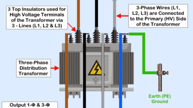
Open Delta Connections of Transformers
Open Delta Connections of Transformers
Suppose you have three single-phase transformers of 5 KVA each. They are connected in (both primary & secondary sides) in delta, then we can say it is a closed delta system of Transformers.
How much 3Ø balanced load can be supplied by this combination?
The answer is, 15 KVA, three-phase balanced load can be supplied by this combination.
In this case, Load on each transformer will be 5 KVA, i.e. each transformer is operating at its rated capacity.
Now, Let one transformer is damaged and disconnected due to repairing purpose. Will the remaining system work? The remaining system will work as an open delta system (i.e. in the open delta system, we have two single-phase transformers). Open delta system is also called V-V system.
Now, how much 3Ø balanced load can be supplied by this system?
The answer is, now we have two single-phase transformers of 5 KVA each, but we are not able to supply 10 KVA, balanced load.
This combination can supply a maximum of 8.66 KVA 3Ø balanced load. Load on each transformer will be 5 KVA, i.e. each transformer is operating at its rated capacity.
The efficiency of this (open delta) system will be less as compared to the closed delta system. Because, in open delta system, both the transformers are operating at rated capacity (i.e. 5 KVA), so their losses will be as per full load losses, but the output is reduced (output is 8.66 KVA instead of 10 KVA).
If the output of open delta, in this case, is possible to be 10 KVA, then the efficiency of closed delta & open delta systems will be same, and in the whole world, to supply three phase load, instead of three single-phase transformers, two single-phase transformers may be sufficient.
So, you can understand with three 5 KVA transformers, we can supply 15 KVA load, but with the remaining two 5 KVA transformers, we cannot supply 10 KVA load. We are able to supply less than 10 KVA load, due to this reason, the efficiency of an open delta system will be less as compared to the closed delta system.
So, we are able to continue three phase supply as an open delta system but at reduced efficiency.
How the value 8.66 KVA is calculated in the above discussion?
It is as follows:
Capacity of open delta system = √3 x rating of one transformer = √3 x 5 KVA= 8.66 KVA.
OR,
Capacity of open delta system = 0.577 x rating of closed delta system=0.577 x 15 KVA= 8.66 KVA.
Now, we will explain, aforesaid calculation with the following diagram:
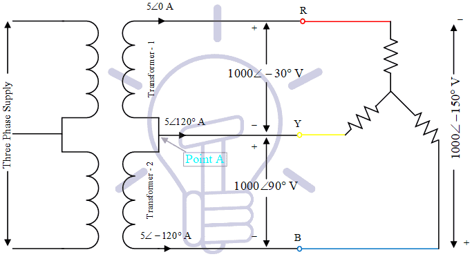
It is the circuit diagram of an open delta system. In this diagram three phase unity PF load (resistive load) is supplied by two transformers. It can be observed that at point ‘A’ KCL is satisfied. Also recall that phase difference between Line current and Line-Line voltage (phase to phase voltage) is 30°, the same is reflected in the diagram also.
It can be observed, three-phase load is consuming power (in KVA) =√3VLIL = √3 x 1000 x 5 = 8660 VA = 8.66 KVA
Load on each transformer is 5 KVA (Voltage across each transformer is 1000 V, current flowing through each transformer is 5 A). Therefore each transformer is operating at 5 KVA, but total load supplied is 8.66 KVA (not 10 KVA)
If you will calculate load in KW (active power) then you will find that Load on both the transformers will be equal to three phase load (in KW).
From the diagram, the load supplied by transformer-1 is: ![]()
Load supplied by transformer-2 is:![]()
(In the calculation of transformer-2, Sign of current is minus (it is -5 instead of 5), readers can understand it themselves)
So, it can be seen that load on both the transformers is 4330.13 Watt (4.33 KW) and they are supplying a total 3Ø load of 8.66 KW.
One transformer is generating reactive power (2500 VAR or 2.5 KVAR), another is consuming the same amount of reactive power. Reactive power consumed by the load is zero (as it is resistive load, power factor is unity). Since there is an exchange of reactive power between both the transformers, due to this reason total KVA rating of transformers is more than KVA rating of load.
Suppose the load is not resistive, its power factor is cosø, then Power factor of both the transformers can be calculated to be cos(30+ø) and cos(30-ø). On that basis power supplied by transformers can be calculated.
Related Posts: