Kirchhoff’s Current & Voltage Law (KCL & KVL) | Solved Example
KCL & KVL – Kirchhoff’s First & Second Laws with Solved Example
A German Physicist “Robert Kirchhoff” introduced two important electrical laws in 1847 by which, we can easily find the equivalent resistance of a complex network and flowing currents in different conductors. Both AC and DC circuits can be solved and simplified by using these simple laws which are known as Kirchhoff’s Current Law (KCL) and Kirchhoff’s Voltage Law (KVL).
Also note that KCL is derived from the charge continuity equation in electromagnetism while KVL is derived from Maxwell – Faraday equation for static magnetic field (the derivative of B with respect to time is 0).
Kirchhoff’s Current Law (KCL):
According to KCL:
At any moment, the algebraic sum of flowing currents through a point (or junction) in a network is Zero (0) or in any electrical network, the algebraic sum of the currents meeting at a point (or junction) is Zero (0). This law is also known as Point Law or Current law.
In any electrical network, the algebraic sum of incoming currents to a point and outgoing currents from that point is Zero. Or the entering currents to a point are equal to the leaving currents of that point.
In other words, the sum of the currents flowing towards a point is equal to the sum of those flowing away from it. Or the algebraic sum of the currents entering a node equals the algebraic sum of the currents leaving it.
Explanation of KCL:
Suppose some conductors are meeting at a point “A” as shown in fig 1.a. In some conductors, currents are incoming to the point “A” while in other conductors, Currents are leaving or outgoing from point “A”.
Consider the incoming or entering currents as “Positive (+) towards point “A” while the leaving or outgoing currents from point “A” is “Negative (-)”.
then:
I1 + (–I2) + (–I3) + (–I4) + I5 = 0
OR
I1 + I5 – I2 – I3 – I4 = 0
OR
I1 + I5 = I2 + I3 + I4 = 0
i.e.
Incoming or Entering Currents = Leaving or Outgoing Currents
Or
ΣI Entering = ΣI Leaving
For instance, 8A is coming towards a point and 5A plus 3A are leaving that point in fig 1.b, therefore,
8A = 5A + 3A
8A = 8A.

Kirchhoff’s Voltage Law (KVL):
The Kirchhoff’s second law or KVL stated that;
In any closed path (or circuit) in a network, the algebraic sum of the IR product is equal to the EMF in that path.
In other words, in any closed loop (which is also known as Mesh), the algebraic sum of the EMF applied is equal to the algebraic sum of the voltage drops in the elements. Kirchhoff’s second law is also known as Voltage Law or Mesh law.
ΣIR= ΣE
Explanation of KVL:
A closed circuit is shown in fig which contains two connections of batteries E1 and E2. The overall sum of E.M.F’s of the batteries is indicated by E1-E2. The imaginary direction of current is also shown in the fig.
E1 drives the current in such a direction which is supposed to be positive while E2 interferes in the direction of current (i.e. it is in the opposite direction of the supposed direction of current) hence, it is taken as negative. The voltage drop in this closed circuit depends on the product of Voltage and Current.
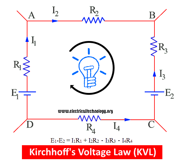
The voltage drop occurs in the supposed direction of current is known as Positive voltage drop while the other one is negative voltage drop.
In the above fig, I1R1 and I2R2 are positive voltage drops and I3R3 and I4R4 are negative V.D.
If we go around the closed circuit (or each mesh), and multiply the resistance of the conductor and the flowing current in it, then the sum of the IR is equal to the sum of the applied EMF sources connected to the circuit.
The overall equation for the above circuit is:
E1 – E2 = i1R1 + i2R2 – i3R3 – i4R4
If we go in the supposed direction of the current as shown in the fig, then the product of the IR is taken as positive otherwise negative.
Good to Know:
Direction of the Current:
It is very important to determine the direction of current whenever solving circuits via Kirchhoff’s laws. Same like the case of election current and conventional current.
The direction of current can be assumed through clockwise or anticlockwise direction. Once you select the custom direction of the current, you will have to apply and maintain the same direction for the overall circuit until the final solution of the circuit.
If we got the final value as positive it means, the supposed direction of the current was correct. In case of negative values, the current of the direction is reversed as compared to the supposed one then.
Circuit Analysis by Kirchhoff’s Laws
Solved Example on KCL and KVL (Kirchhoff’s Laws)
Example:
Resistors of R1= 10Ω, R2 = 4Ω and R3 = 8Ω are connected up to two batteries (of negligible resistance) as shown. Find the current through each resistor.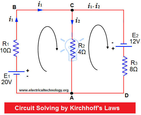
Solution:
Assume currents to flow in directions indicated by arrows.
Apply KCL on Junctions C and A.
Therefore, current in mesh ABC = i1
Current in Mesh CA = i2
Then current in Mesh CDA = i1 – i2
Now, Apply KVL on Mesh ABC, 20V are acting in clockwise direction. Equating the sum of IR products, we get;
10i1 + 4i2 = 20 … (1)
In mesh ACD, 12 volts are acting in clockwise direction, then:
8(i1 – i2) – 4i2 = 12
8i1 – 8i2 – 4i2 = 12
8i1 – 12i2 = 12 … (2)
Multiplying equation (1) by 3;
30i1 + 12i2 = 60
Solving for i1
30i1 + 12i2 = 60
8i1 – 12i2 = 12
___________
38i1 = 72
The above equation can be also simplified by Elimination or Cramer’s Rule.
i1 = 72 ÷ 38 = 1.895 Amperes = Current in 10 Ohms resistor
Substituting this value in (1), we get:
10 (1.895) + 4i2 = 20
4i2 = 20 – 18.95
i2 = 0.263 Amperes = Current in 4 Ohms Resistors.
Now,
i1 – i2= 1.895 – 0.263 = 1.632 Amperes
Applications of Kirchhoff’s Laws
- Kirchhoff’s laws can be used to determine the values of unknown values like current and Voltage as well as the direction of the flowing values of these quintets in the circuit.
- These laws can be applied on any circuit* (See the limitation of Kirchhoff’s Laws at the end of the article), but useful to find the unknown values in complex circuits and networks.
- Also used in Nodal and Mesh analysis to find the values of current and voltage.
- Current through each independent loop is carried by applying KVL (each loop) and current in any element of a circuit by counting all the current (Applicable in Loop Current Method).
- Current through each branch is carried by applying KCL (each junction) KVL in each loop of a circuit (Applicable in Loop Current Method).
- Kirchhoff’s Laws are useful in understanding the transfer of energy through an electric circuit.
Good To Know: These rules of thumbs must be taken into account while simplifying and analyzing electric circuits by Kirchhoff’s Laws:
Limitations of Kirchhoff’s laws:
- KCL is applicable on the assumption that current flows only in conductors and wires. While in High Frequency circuits where, parasitic capacitance can no longer be ignored. In such cases, Current can flow in an open circuit because in these cases, conductors or wires are acting as transmission lines.
- KVL is applicable on the assumption that there is no fluctuating magnetic field linking the closed loop. While, in presence of changing magnetic field in a High Frequency but short wave length AC circuits, the electric field is not a conservative vector field. So, the electric field cannot be the gradient of any potential and the line integral of the electric field around the loop is not zero, directly contradicting KVL. That’s why KVL is not applicable in such a condition.
- During the transfer of energy from the magnetic field to the electric field where fudge has to be introduced to KVL to make the P.d (potential differences) around the circuit equal to 0.
Related Posts about electric circuits analysis theorems:
- Thevenin’s Theorem. Step by Step Procedure with Solved Example
- Norton’s Theorem. Easy Step by Step Procedure with Example (Pictorial Views)
- SUPERNODE Circuit Analysis | Step by Step with Solved Example
- SUPERMESH Circuit Analysis | Step by Step with Solved Example
- Maximum Power Transfer Theorem for AC & DC Circuits
- Compensation Theorem – Proof, Explanation and Solved Examples
- Substitution Theorem – Step by Step Guide with Solved Example
- Millman’s Theorem – Analyzing AC & DC Circuits – Examples
- Superposition Theorem – Circuit Analysis with Solved Example
- Tellegen’s Theorem – Solved Examples & MATLAB Simulation
- Voltage Divider Rule (VDR) – Solved Examples for R, L and C Circuits
- Current Divider Rule (CDR) – Solved Examples for AC and DC Circuits
- Ohm’s Law: Simple Explanation with Statement and Formulas
- Star to Delta & Delta to Star Conversion. Y-Δ Transformation


electrical advance system fault analysis
There’s a mistake in the solved example..
I’m the second loop, the equation should be
8(i1–i2)- 4i2= 12
The -4i2 is missing
Thanks for correction.
according to Kirchhoff’s voltage law the voltage drops is equal to the resultant e.m.f acting on that loop. So following the current in the second loop, there was a voltage lift at the at the second supply voltage thus having it as positive 12 (+12). Then the current went from this to the 8ohm resistor which causes a voltage drop thus making it -8(i1-i2). Then loop continued to the 4ohm resister which had a voltage drop from positive to negative thus having -4i2
so for me the equation should look like this 12-8(i1-i2)-4i2=0 so that 12 -8i1+8i2-4i2=0
which is 12-8i1+4i2=0 so the final equation for loop two will be
12=8i1-4i2
if I’ve done any mistake please correct me
in kvl method why we are going to multiply the equation 1 by 3?
Now, Apply KVL on Mesh ABC, 20V are acting in clockwise direction. Equating the sum of IR products, we get;
10i1 + 4i2 = 20 ……………. (1)
In mesh ACD, 12 volts are acting in clockwise direction, then:
8(i1–i2) – 4i2= 12
8i1 – 8i2 – 4i2= 12
8i1 – 12i2 = 12 ……………. (2)
Multiplying equation (1) by 3;
30i1 + 12i2 = 60
It is a simple elimination… You can Also do it by Cramer’s Rule…
bcz we have to just cancel out i2 so we can find out i1 value
How do you now with what do you need to eliminate the equation?Why 3 and not 2 for example?
please, I need the final answer of this equation
Whay you multiple by 3 .i can’t get it plizzz tell me …whay only 3 whay not 2&3&4&5&3 some like
@Selva
We wanted to cancel out the i2 term in the first equation.
That action comes from a Linear Algebra technique called Solving Systems of Equations, which says that we can multiply one value in one equation as long as we multiply all other values in that same equation by the same multiplication amount.
For example, we start with equation 5i1+10i2 = 15.
Let’s say we want 10i2 to become 30i2. We can multiply 3*10i2, BUT we must also multiply all the other terms in the same equation by that same multiplier. So:
5i1 + 3*10i2 = 15 (after simplifying, it’s 5i1+30i2=15) is wrong, but
3*5i1 + 3*10i2 = 3*15 (after simplifying, it’s 15i1+30i2=45) is correct.
So, we are allowed to scale up an individual equation without violating the “left side EQUALS right side” property.
We can get a specific variable to have a certain amount in one equation, but how is that useful? It’s useful because we don’t just have one equation, we have multiple! With multiple equations, we’re trying to solve the variables to see what value each of them is. To do this, it’s best to get one of the variables to become the value 0, but we’re not allowed to multiply by 0 nor delete/subtract that element out of existence. We ARE allowed to add entire equations to each other (notice how I said *entire* equations and not just *parts* of equations).
Using the earlier tactic of single-equation-scaling and this tactic of add-entire-equations-together, we can try to get a single variable (like i2) to have equal value in two equations and one equation just be the negative of the other.
The problem’s equations:
10i1 + 4i2 = 20 (equation 1)
8i1 – 12i2 = 12 (equation 2)
We can sum the equations together to get the simplified equation (10i1+8i1)+(4i2+ -12i2) = (20+12), which is 18 i1 – 8 i2 = 32.
As you can see, we still have both variables in the added-together equation and are no closer to finding each variable’s value, so immediately adding the equations is useless in this case.
Instead of immediately adding the equations, let’s scale one of the equations and then add the equations together.
We notice that both equations 1 and 2 have an i2 variable AND that one is positive while the other is negative. Let’s try to make the i2 variable in both equations have the same value while preserving that one-positive-and-one-negative relationship. How do we do that? The easiest thing to do would be to multiply +4i2 by 3 to get it to become +12i2, so that adding both equations together results in (3 * 4 i2)+(-12 i2) = 0 i2 = 0. However, remember that we must scale the entire equation (not just one part of an equation), and that we must add whole/entire multiple equations (not just adding one part of multiple equations).
After multiplying the entire equation1 by the value 3 to get the scaled i2 variable to match the size of the i2 variable in equation 2, we get:
30i1 + 12i2 = 60 (equation 1)
8i1 – 12i2 = 12 (equation 2)
Now we have equal (valued) and opposite(ly signed) i2 variables in the equations, so now when we sum the equations together, the i2 term will disappear like we originally wanted.
Equation1 + Equation2:
= (sum of i1 terms) + (sum of i2 terms) = (sum of constant (non-variable) terms on the right side)
=> (30 i1 + 8 i1) + (12 i2 + -12 i2) = (60+12)
=> 38 i1 + 0 i2 = 72
=> 38 i1 = 72
=> i1 = 72/38
=> i1 = roughly 1.894
So, now we know that i1 has about 1.894 Amperes of current running through the location/region at i1.
We can now plug this value into the original two equations (not the modified versions we created) to solve for i2.
how can i determine the current direction if i am not given
simple you can make your own assumption by drawing direction of current from any junction you want
If your answer will be nagative you have to oppose the direction you assumed
good, excellent & lucid way to explain them.
quite good
I enjoyed the explanation of Kcl and kvl.
Can you solve questions of a circuit which has more two sources of voltage.
little bit confused
Simply nice
I’m not sure about current law
good example .please uplode more question about this topic ,mean kvl or kcl
i didn’t touch ur idea about kvl.
I think we just needed here to apply kvl in each mesh
i1(10) + (i1 – i2)(4)= 20
i2(8) + (i2 – i1)(4)= 12
now needed to solve these two equations by crammer’s rule or by simplification…
Thank your for the details and infor about KVL and KCL.
good
I would like to object to this statement in your article: The voltage drop in this closed circuit depends on the product of Voltage and Current.