Maintenance of Transformer – Power Transformers Maintenance, Diagnostic & Monitoring
Maintenance of Power Transformer – Transformer Diagnostic and Monitoring
Introduction
Being transformers static machines without any moving and turning parts, they are very reliable machines, and if maintained properly, can last for 40 years or more. Also they do not trip or blow when oven-stressed (except under extreme conditions), transformers are frequently overloaded and allowed to operate well beyond its capacity.
However, use and ageing of electrical installations, similar to other installations, is an origin of normal deterioration in electrical equipment that can be accelerated by factors such as a hostile environment, overload, or severe duty cycle.
Other causes of deterioration may be load changes/additions, circuit changes, improperly set/selected protective devices and changing voltage conditions.
However, equipment failure is not inevitable if a checking and preventive maintenance program is established.
- Also read: Current Transformers (CT) – Types, Characteristic & Applications
Establishment of a regular preventive maintenance program may minimize the risk of equipment failure and the resulting problems of that failure, the detection of latent faults and the first step for troubleshooting.

Visual Inspection of Power Transformer
The most frequent attention given to power transformers is visual inspection, which involves mainly checking the transformer’s general exterior condition and cooling system.
Power transformers must be inspected regularly so that problems can be detected early and corrected before major repairs are needed.
Inspections are done routinely, usually once a week, although the frequency can vary from company to company and among transformers. For example, a transformer may be checked more often if there is reason to believe that a problem is developing.
Table 1 shows the types of visual inspections required to control the general exterior condition and cooling system.
Click image to enlarge
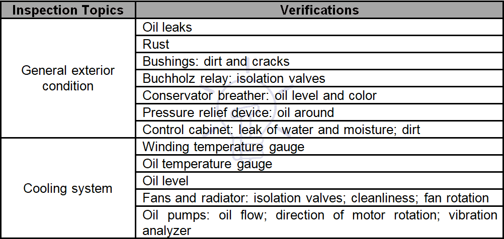 Table 1 – Visual inspection of transformers
Transformer Diagnostic and Monitoring
Transformer monitoring refers to on-line measurement techniques, where the emphasis is on collecting pertinent data on transformer integrity and not on interpretation of data.
Transformer monitoring techniques vary with respect to the sensor used, transformer parameters measured, and measurement techniques applied. Since monitoring equipment is usually permanently mounted on a transformer, it must also be reliable and inexpensive.
Winding and On-Load Tap Changers (OLTC) failures dominate; consequently, the focus of most monitoring techniques is to collect data from parameters that can be used to assess the condition of winding and tap changers.
Dissolved gases in oil and partial discharges (PD) are common parameters monitored related to winding and insulation condition.
Temperature and vibration monitoring are commonly used for assessing OLTC condition.
Figure 1 shows the statistics distribution of failures in an oil-immersed transformer.
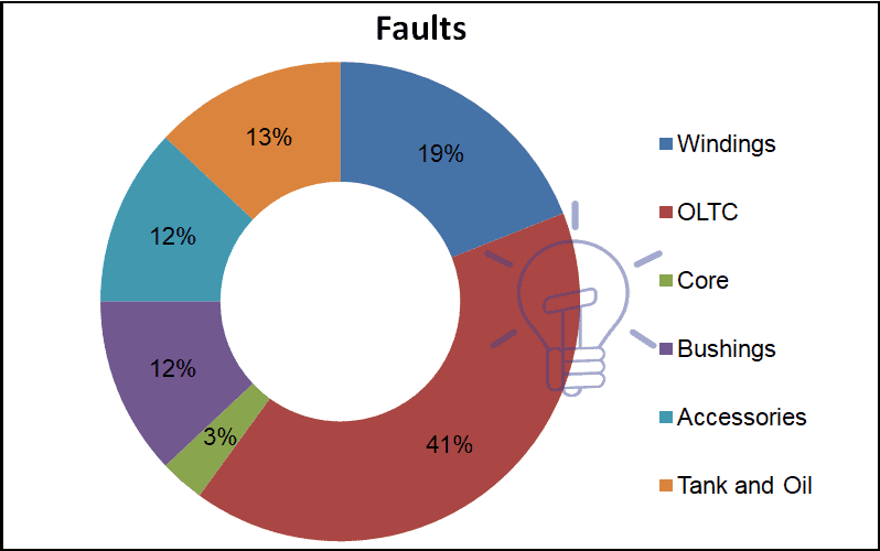 Figure 1 – Statistics distribution of failures in an oil-immersed transformer
Common parameters used to monitor windings and insulation status is PD and dissolved gases in the oil; in what concerns monitoring of OLTC temperature and vibration are used.
Main monitoring units used for transformers diagnostics are:
- Oil temperature monitoring unit.
- Oil level monitoring sensor.
- Gas-in-oil monitoring unit.
- OLTC operation monitoring sensor.
- Overload monitoring unit.
Data from monitoring sensors and units are transformed into digital and analogue signals and establish a real-time basis communication with a man-machine interface and data recording.
Dissolved gas-in-oil analysis is an effective diagnostic tool for determining problems in transformer operation.
However, this analysis is typically performed off-post, where sophisticated (and usually expensive), equipment is used to determine gas content.
To reduce the risk of missing incipient faults due to long sampling intervals, monitoring techniques are being developed to provide warnings with respect to changes in gas types and concentrations observed within a transformer. Conventional dissolved gas-in-oil analysis is performed after a warning is issued. Several transformer gases and corresponding sources are listed in Table 2.
Click image to enlarge
 Table 2 – Transformer gases and sources
By extracting the gas dissolved in the insulation oil of the main transformer and measuring the amounts of the six gas components at their low level, it is possible to detect local overheating or partial electric discharge in the unit depending on the analyzer data and to prevent any accidents before they occur.
Schedule of Preventive Maintenance Actions and Inspection of Transformer
Frequency of maintenance shall be established taking into account equipment reliability requirements and the manufacturers’ manuals and recommendations.
Maintenance activities may be planned for each segment of the installation at different periods, but major industries usually once or twice a year have a global shut-down for maintenance purposes.
NETA[1] Standard MTS-2007 Appendix B presents the time-based maintenance schedule and matrix shown in Table 3. The application of the matrix is recognized as a guide only.
Specific condition, criticality, and reliability must be determined to correctly apply the matrix. Application of the matrix, along with the culmination of historical testing data and trending, should provide a quality electrical preventive maintenance program.
Click image to enlarge
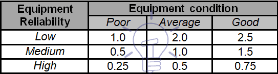 Table 3 – Maintenance Frequency Matrix
For transformers the minimum frequency maintenance tests are defined at the same standard and shown in Table 4.
Click image to enlarge
 Table 4 – Transformers Frequency of Maintenance Tests (months)
Maintenance activities (visual and mechanical inspection; electrical tests; tests values) for each piece of equipment are defined under NETA Standard ATS-2009 and for transformers can be summarized as shown in Table 5.
Click image to enlarge
 Table 5 – Frequency of tests and inspections for transformers’ maintenance actions
The actions of preventive maintenance of transformers may be synthesized as follows:
- Also read: EMF Equation of Transformer
- Routine inspections
- Sampling collection
- Tests
- Repair
- Minor repairs
- Medium repairs
- Major repairs and overhauls[2]
- Documentation and data record
Table 6 shows usual activities for each type of maintenance actions.
Click image to enlarge
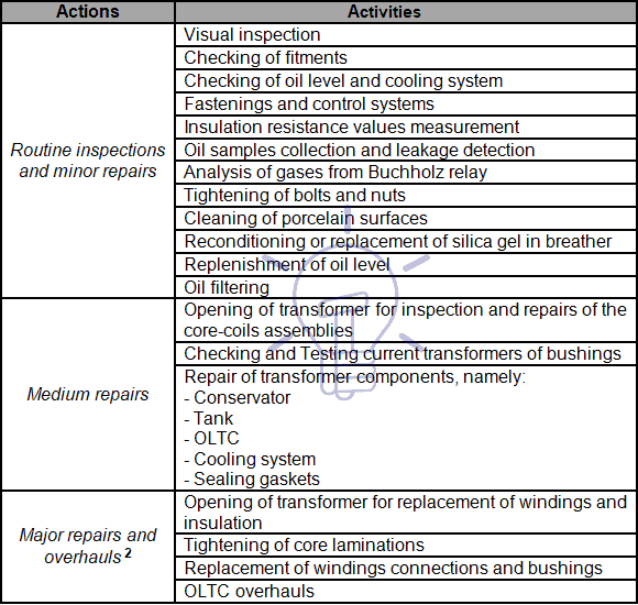 Table 6 – Usual actions of each type of maintenance activities
Apart from special test equipment, the most common portable test equipment used in transformer maintenance activities is:
- Multimeters
- Clamp meters
- Voltage testers
- Instrument transformers test equipment
- Relay and meter test equipment
- Insulation testers (MEGGER[3])
- Earthing test Equipment
- Infrared camera[4] (See Infrared Thermography)
Also read: How to Find the Rating of Transformer in kVA (Single Phase and Three Phase)?
Oil Analysis and Samples
During maintenance period or after a major repair operation, it is necessary to collect a sample of the oil to proceed to the tests defined by IEC[5] Standard 60296 for FAT.
These tests are:
- Interfacial tension (IFT)
- Acidity
- Viscosity
- Density
- Flash point
- Fire point
- Pour point
- Moisture
- Dielectric strength
- Power factor (dielectric losses – tan ∂)
- Color
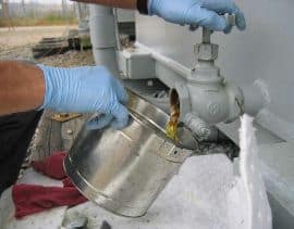
It is necessary to take certain precautions when collecting a sample, in order to avoid the sample to be contaminated.
- 1 – Use the auxiliary sampling valve and do not use small sampling port on side of drain valve (Figure 2).


Figure 2 – Auxiliary sampling valve
- 2 – Flush drain valve
 Figure 3 – Flushing drain valve
- 3 – Flush tubing and syringe and do not pull back on the syringe barrel – apply slight resistance and allow fluid pressure to fill syringe (Figure 4).
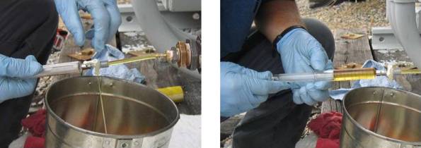
Figure 4 – Flushing tubing and syringe
- 4 – Filled syringe should have no bubbles, but some may form later – do not release these ones.
Also read: Transformers MCQs With Explanatory Answers
Dissolved Gas-in-oil Analysis (DGA)
DGA, one of the most valuable diagnostic tools available, is a procedure used to assess the condition of an oil-filled transformer from an analysis of the gases dissolved in the cooling/insulating medium.
It is a well established technique that is cost effective, providing essential information from a relatively simple, non-destructive test based upon oil sampling.
Whilst the analysis is normally done in a laboratory, on-line devices are also available.
The results reveal much about the health of the oil and of its properties as an insulating medium, including its present condition, any changes that are taking place, the degradation effects of overload, ageing, the inception of minor faults and the most likely cause of major failures.
It should be noted that a severe fault may also produce free gases that may be collect in the Buchholz relay.
Transformer Tests for Maintenance & Diagnoses purposes
Table 7 shows the overall transformer condition assessment methodology, linking routine maintenance and diagnostics.
Click image to enlarge
 Table 7 – Transformer Tests to be performed for maintenance and diagnostics purposes
Bushing Test
For bushings that have a potential tap, both the capacitance between the top of the bushing and the bottom tap (normally called C1) and the capacitance between the tap and ground (normally called C2) are measured.
To determine bushing losses, power factor tests are also performed. C2 capacitance is much greater than C1 capacitance.
Bushings without a potential tap are normally tested from the bushing top conductor to ground.
This test results are compared with factory tests and/or prior tests to determine deterioration.
About 90% of bushing failures may be attributed to moisture ingress evidenced by an increasing power factor.
Sweep Frequency Response Analysis Test
Frequency Response Analysis (SFRA)[6] consists of measuring the impedance of transformer windings over a wide range of frequencies and comparing the results of these measurements to a reference set.
Differences may indicate damage to the transformer, which can be investigated further using other techniques or by an internal examination. The swept frequency method for SFRA requires the use of a network analyzer to generate the signal, take the measurements and manipulate the results.
Ultrasonic and Sonic Fault Detection
This test should be applied when hydrogen is increasing markedly in the DGA.
High hydrogen generation indicates partial discharge occurring inside the transformer. Other gases such as methane, ethane, and ethylene may also be increasing. Acetylene may also be present if arcing is occurring and may also be increasing.
Vibration Analysis
Vibration analysis by itself cannot predict many faults associated with transformers, but it is another useful tool to help determine transformer condition.
Vibration can result from loose transformer core segments, loose windings, shield problems, loose parts, or bad bearings on oil cooling pumps or fans. Extreme care must be exercised in evaluating the source of vibration. Many times, a loose panel cover, door, or bolts/screws lying in control panels, or loose on the outside have been misdiagnosed as problems inside the tank.
Core Insulation Resistance
To do this test, the intentional core ground must be disconnected.
This may be difficult, and some oil may have to be drained to accomplish this.
On some transformers, core grounds are brought outside through insulated bushings and are easily accessed.
Expected values of insulation resistance are:
- New transformers: > 1000 MΩ
- Service-aged transformer: > 100 MΩ
Values between 10 and 100 MΩ reveal possible damage of insulation between the core and the ground and values lower than 10 MΩ can origin destructive circulating currents and must be further investigated.
Infrared Thermography
Infrared thermography (IR) is a noncontact and nondestructive way to detect problems in electrical systems.
All electrical and mechanical equipment emits heat in the form of electromagnetic radiation. Infrared cameras, which are sensitive to thermal radiation, can detect and measure the temperature differences between surfaces.
Abnormal or unexpected thermal patterns can be indicative of a problem with the equipment problems that could lead to a breakdown or failure, or cause a fire.
Commonly Infrared Analysis is done each 2 or 3 years, while equipment is energized and under full load, if possible, but special functioning and environment conditions may require to conduct IR annually.
IR analysis should also be conducted after any maintenance or testing to see if connections that were broken were remade properly. Also, if IR is done during factory heat run, the results can be used as a baseline for later comparison.
The following components of transformers are usually subjected to IR analysis:
- Tank
- Radiators and cooling system
- Bushings
- OLTC
Also read: TRANSFORMER NAMEPLATE (GENERAL REQUIREMENTS).
Tank
Unusually high external temperatures or unusual thermal patterns of transformer tanks indicate problems inside the transformer such as low oil level, circulating stray currents, blocked cooling, loose shields, tap changer problems, etc.
Abnormally high temperatures can damage or destroy transformer insulation and, thus, reduce life expectancy.
An IR inspection can find over-heating conditions or incorrect thermal patterns. IR scanning and analysis requires trained staff experienced in these techniques.
Radiators and Cooling System
Radiators must be examined with an IR camera and compare them with each other.
A cool radiator or segment indicates that a valve is closed or the radiator or segment is plugged.
If visual inspection shows the valves are open, the radiator or segment must be isolated, drained, and removed and the blockage cleared.
A transformer operating with reduced cooling will have its useful life is drastically shortened (an increased operating temperature of only 8 to 10oC will reduce transformer life by one-half).
Bushings and Insulators
a) Oil level
IR scans of bushings can show low oil levels, which would call for immediate De-energizing and replacement.
In general the reason for this is that the seal in the bushing bottom has failed, leaking oil into the transformer. The top seal has probably failed, also allowing air and moisture to enter the top.
Too high oil level in bushings generally means the seal in the bottom of the bushing has failed and oil head from the conservator, or nitrogen pressure, has pushed transformer oil up the bushing.
Another reason a bushing can exhibit high oil level is the top seal leaking, allowing water to enter. The water migrates to the bushing bottom displacing the oil upward.
Over 90% of bushing failures are attributed to water entrance through the top seal.
Bushings commonly fail catastrophically, many times destroying the host transformer and nearby equipment and causing hazards to workers. Previous IR scans of the same bushing must be compared with the current scan.
b) Bushing connections
Bushings have two internal connections, one in the head and another much deeper inside connected to the transformer coils.
Both will show up externally, but the head connection will be on the upper part of the bushing while the coil connection will be at the base of the bushing.
Problems with cracks have been found in certain insulators that affect the electrical and mechanical strength of the insulator.
When surface moisture is present, a very small discharge current flows over the surface of the insulator raising the temperature by one or two degrees. When an insulator is cracked the discharge current flows down the crack and not over the surface and the insulator shows up slightly colder.
When the crack becomes severe enough a temperature increase may become evident.
OLTC (On-Load Tap Changers)
The temperature of the OLTC cover should be the same temperature as the transformer itself.
The source of the heat is inside the OLTC casing and is considerably hotter than the indicated temperature.
An external OLTC compartment should be no warmer than the body of the transformer. If it is warmer, it indicates probable heating of the internal tap connections.
One difficulty with tap inspections is that all taps are not connected at the time of the inspection so results may not be conclusive.
[1]NETA: InterNational Electrical Testing Association (USA).
[2]To be carried out after a severe internal fault or each 8-10 years of continuous functioning, namely when the transformer is subjected to severe overload cycles or external short-circuit. These activities must be performed by specialized personnel.
[3] MEGGER is a trade mark, but this equipment is known under this name.
[4] See Chapter 7 i.e. Infrared Thermography.
[5] IEC: International Electrotechnical Comission.
[6] Only if this test was performed during FAT – Factory Acceptance Tests.


Hello, this information is very amazing !
Thanks, for providing this useful information. If you want any query about transformer visit my site.