Power Transformer Protection and Faults
Power Transformer Protection and Types of Faults
In our previous post, we have already discussed about electrical protection Systems, devices and units. Today, we will discuss about different types of transformer protection and faults in details.
Power Transformer Faults
Transformers are vital equipment in transmission and distribution network and so the protection against internal and external faults is a very important factor in the design of those networks.
Transformers faults may occur:
- In the dielectric (insulating) materials, namely in the oil.
- In the windings.
- In the core (less frequent).
Oil & Winding Insulation Faults
Transformer oils are designed to provide electrical insulation under high electrical fields; any significant reduction in the dielectric strength may indicate that the oil is no longer capable of performing this vital function.
Some of the things that can result in a reduction in dielectric strength include polar contaminants, such as water, oil degradation by products and cellulose paper breakdown.
Transformer faults may occur in the oil due to gas formation, ageing, contamination with air and lack of level and pressure.
In the event of a minor fault like damage to core bolt insulation, local overheating, etc., the arcing causes slow generation of gas in the oil.
All faults in transformer core and windings result in the localized heating and breakdown of oil.
When the fault is of very minor type such as hot joint, gas is released slowly and rises towards conservator.
A major fault where severe arcing takes place causes rapid release of large volume of gas and oil vapor.
This violent evolution of gas and oil vapor does not have time to escape and instead builds up pressure and bodily displaces the oil, causing surge of oil to the conservator.
Faults may also occur in the windings insulation material, as a consequence of oil failure, ageing, overheating and insulation breakdown.
Core Faults
If any portion of the core insulation becomes defective or the laminated structure of the core is bridged by any conducting material which can permit sufficient eddy current to flow, it will cause serious overheating.
The insulated core bolts are used for tightening the core. If the insulation of these bolts fails and provides easy path for stray current, this will lead to overheating.
Mechanical impacts during handling and transportation may apply to the transformer an equivalent force above 3g (where g is the gravidity acceleration; g = 9.81 m/s2.), which can cause distortion of the core.
Windings Faults
Common windings faults are:
- Faults between primary and secondary windings (short circuit) of the same phase.
- Short-circuit between the turns of the winding.
These faults usually are a result of dielectric failure, both between windings and between the turns of the same winding, due to ageing of insulation material, which may increase due to overloads.
It also must be considered that the windings are subject to both radial and axial forces related to the current and flux interactions. Radial forces in the inner winding (normally the LV winding) are in compression while the outer winding (normally the HV winding) forces are in tension.
Design of the windings and bracing must consider the magnitude of these forces and provide adequate strength to withstand them without significant mechanical deformation which could result in a dielectric failure.
Also mechanical impacts during handling and transportation may apply to the transformer an equivalent force above 3g, which can cause distortion and/or displacement of the windings and decrease of the insulation of the windings.
Overload Faults
The loading of transformer is decided by permissible temperature rise of windings and oil. Permissible oil temperature is 65 °C and hot spot temperature of the winding is 80 °C at rated load.
As the load of the transformer does not remain steady and varies according to load curve, the loading of transformer becomes an important operating problem.
The rated output of a power transformer is mentioned on its name plate with reference to specified temperature rise under specified test conditions.
The output which can be obtained from a transformer without causing undue deterioration of the insulation may be either more or less than the name plate rating depending upon the operating conditions, such as ambient temperature, initial loading, cooling provision, life expectancy, etc.
Overheating Faults
Overheating in transformer may be caused by overloads above the permissible overloads specified by the manufacturers, according to IEC Standards (60354 for oil-filled transformers and 60905 for dry type transformers), and external faults, such as short-circuits on installations downstream. Most of these faults may be limited by proper maintenance of a transformer.
Overheating may cause a breakdown of the insulation of the windings.
Power Transformer Protection
Built-On Protection
Transformers are provided with bullet on (internal protections) for dielectric failure (formation of gas), temperature, oil pressure, level, winding temperature and on load tap changer.
According to the construction type of transformers the following protections must be provided:
Oil-filled transformers with conservator
- Buccholz relay for dielectric failure (2 steps: alarm and trip)
- Oil pressure and level switches (2 steps: alarm and trip)
- Thermostat for oil temperature (2 steps: alarm and trip)
- On-load tap changer protection (2 steps: alarm and trip)
Buccholz relay has multiple methods to detect a failing transformer.
- On a slow accumulation of gas, due perhaps to slight overload, gas produced by decomposition of insulating oil accumulates in the top of the relay and forces the oil level down. A float switch in the relay is used to initiate an alarm signal. Depending on design, a second float may also serve to detect slow oil leaks.
- If an arc forms, gas accumulation is rapid, and oil flows rapidly into the conservator. This flow of oil operates a switch attached to a vane located in the path of the moving oil.
Buchholz relays have a test port to allow the accumulated gas to be withdrawn for testing. Flammable gas found in the relay indicates some internal fault such as overheating or arcing, whereas air found in the relay may only indicate low oil level or a leak.
For transformers equipped with cooling fans and pumps, the temperature devices are used to automatically start and stop the forced cooling. They are also equipped to initiate an alarm and a trip for very high transformer temperatures.
Oil-filled sealed transformers
- Gas detection and oil level, pressure and temperature in one single equipment (DGPT 2 – Detection of Gas, Pressure and Temperature) with 2 levels (alarm and trip)
Dry type transformers
- Temperature of windings with 2 levels (alarm and trip) – resistance temperature detector PT 100 (platinium probe) or PTC (“Positive Temperature Coefficient”), that is a thermistor (semi conductive material sensitive to temperature).
These protections have a direct action on the tripping coils of the circuit breakers.
Differential Protection
The ideal way of protecting any piece of power system equipment is to compare the current entering that piece of equipment, with the current leaving it.
Under normal healthy conditions the two are equal. If the two currents are not equal, then a fault must exist.
This is done through “differential protection” (ANSI / IEEE / IEC code 87T), which diagram is shown in Figure 1 and the functioning principle is based in Kirchhoff current law.
IEC: International Electrotechnical Comission. ANSI: American National Standards Institute. IEEE: Institute of Electrical and Electronic Engineers.

Figure 1 – Differential protection diagram
EHV and HV transformers and autotransformers for volatges above 49.5 kV and MV transformers with rated power above 3-4 MVA have usually as main protection a differential protection for winding faults – short-circuits between turns of a winding or between windings that correspond to phase-to-phase or three-phase type short-circuits.
If there is no earthing / grounding connection at the transformer location point, this protection can also be used to protect against earth faults.
If the earth fault current is limited by impedance, it is generally not possible to set the current threshold to a value less than the limiting current.
This protection is connected to current transformers CT (Current Transformers) at both side of the transformer (primary and secondary), as it was shown in Figure 1.
The use of transformer differential protection poses some problems that must be taken into account:
Problem relating to the transformation ratio and the coupling method
The primary and secondary currents have different amplitudes owing to the transformation ratio and different phases depending on the coupling method (delta-star transformer makes a phase displacement of 30°). Therefore, the current values measured must be readjusted so that the signals compared are equal during normal operation.
This is done using matching auxiliary transformers whose role is to balance the amplitudes and phases.
When one side of the transformer is star-connected with an earthed neutral, the matching transformers on this side are delta-connected, so that the residual currents that would be detected upon occurrence of an earth fault outside the transformer are cleared.
Figure 16 shows an example of the connection of the differential protection, using matching auxiliary transformers.
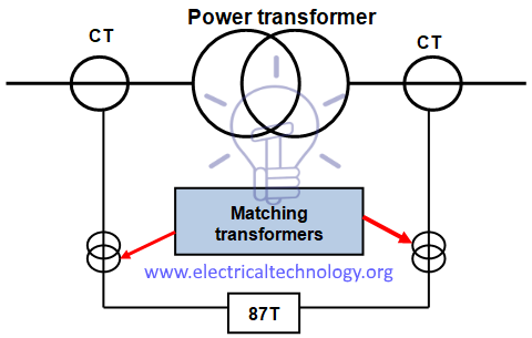 Figure – Transformer differential protection diagram
Nowadays, with electronic and microprocessed protection units, this compensation is done through software.
Function of the protection is based on the transformation ratio “n” that can be expressed by the equation:
n = (U1 / U2) = (I2 / I1)
(U1: primary voltage; U2: secondary voltage; I1: primary current; I2: secondary current).
The above relation is a consequence of the equation of the rated power (S) of the transformer:
S = √3 x U1 x I1 = √3 x U2 x I2
Problem relating to the transformer inrush current
Transformer switching causes a very high transient current (from 8 to 15 In), which only flows through the primary winding and lasts several tenths of a second.
It is thus detected by the protection as a differential current and it lasts far longer than the protection operating time (30 ms). Detection based only on the difference between the transformer primary and secondary currents would cause the protection to be activated. Therefore, the protection must be able to distinguish between a differential current due to a fault and a differential inrush current.
Experience has shown that the inrush current wave contains at least 20% of second harmonic components (current at a frequency of 100 Hz), while this percentage is never higher than 5% upon occurrence of an overcurrent due to a fault inside the transformer.
The protection must therefore simply be locked when the percentage of second harmonic component in relation to the fundamental harmonic component (current at 50 Hz) is higher than 15%, i.e., “I2 / I1 > 15%”.
Problem relating to the magnetizing current upon occurrence of an overvoltage of external origin
Magnetizing current, or exciting current, is the current that flows through the primary winding of a power transformer when no loads are connected to the secondary winding; this current establishes the magnetic field in the core and furnishes energy for the no-load power losses in the core. It is responsible for “iron losses”.
The magnetizing current constitutes a difference between the transformer primary and secondary currents. It is therefore detected as a fault current by the differential protection even though it is not due to a fault.
In normal operating conditions, this magnetizing current is very low and does not reach the protection operating threshold.
However, when an overvoltage occurs outside the transformer, the magnetic material saturates (in general the transformers are dimensioned to be able to operate at saturation limit for the nominal supply voltage), and the magnetizing current value greatly increases. The protection operating threshold can therefore be reached.
Experience has shown that the magnetizing current due to the magnetic saturation has a high rate of fifth harmonic components (current at a frequency of 250 Hz).
Transformer differential therefore requires fairly complex functions as it must be able to measure second and fifth harmonic current or, in order to avoid measuring fifth harmonic currents, it must be able to detect overvoltages of external origin.
The characteristics of transformer differential protection are related to the transformer specifications:
- Transformation ratio
- Vector group
- Inrush current
- Permanent magnetizing current
Over-Current Protection
MV transformers with rated power up to 2.5 MVA are usually only protected against overcurrents using over current relays.
- Three phase or phase-to-phase short circuit, instantaneous (ANSI/IEEE/IEC code 50).
- Three phase or phase-to-phase short circuit, time delayed (ANSI/IEEE/IEC code 51).
- Phase-to-earth short circuit, instantaneous (ANSI/IEEE/IEC code 50N).
- Phase-to-earth short circuit, time delayed (ANSI/IEEE/IEC code 51N).
This set of protections is used on HV and MV transformers with rated power above 3-4 MVA as a “back-up” protection, in addition to the differential protection.
In some installations and networks MV transformers with rated power up to 630 kVA may be protected against overcurrents by fuses associated to switch-disconnectors, as shown in Figure 2.
In these situations the switch-disconnectors must have a tripping coil to allow the action of the built-on protections of transformers.
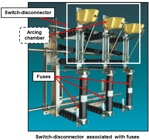 Figure 2 – Switch-disconnector associated with fuses
Fuses must have a mechanical latch to indicate the fusion and to provoke three-pole opening of the switch-disconnector, to avoid the functioning of the installation only with two phases.
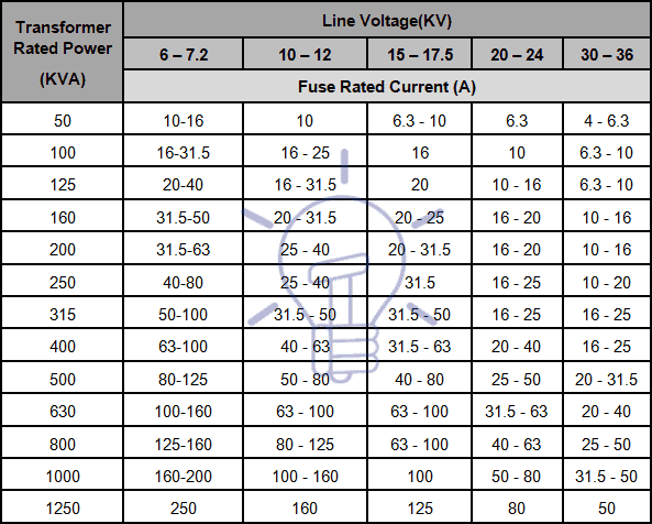
Manufacturers provide tables to choose the rated current of a fuse, taking into account the rated voltage and power, like the one shown in the Table 1, according to IEC standards.
Tables vary from manufacturer to manufacturer, according to the standards used, being recommended to use the table provided by the selected manufacturer.
Table 1 – Rated current of fuses for power transformers protection
|
Transformer Rated Power (KVA) |
Line Voltage(KV) | ||||
| 6 – 7.2 | 10 – 12 | 15 – 17.5 | 20 – 24 | 30 – 36 | |
| Fuse Rated Current (A) | |||||
| 50 | 10-16 | 10 | 6.3 – 10 | 6.3 | 4 – 6.3 |
| 100 | 16-31.5 | 16 – 25 | 16 | 10 | 6.3 – 10 |
| 125 | 20-40 | 16 – 31.5 | 20 | 10 – 16 | 6.3 – 10 |
| 160 | 31.5-50 | 20 – 31.5 | 20 – 25 | 16 – 20 | 10 – 16 |
| 200 | 31.5-63 | 25 – 40 | 20 – 31.5 | 16 – 20 | 10 – 16 |
| 250 | 40-80 | 25 – 40 | 31.5 | 16 – 25 | 10 – 20 |
| 315 | 50-100 | 31.5 – 50 | 31.5 – 50 | 16 – 25 | 16 – 25 |
| 400 | 63-100 | 40 – 63 | 31.5 – 63 | 20 – 40 | 16 – 25 |
| 500 | 80-125 | 50 – 80 | 40 – 80 | 25 – 50 | 20 – 31.5 |
| 630 | 100-160 | 63 – 100 | 63 – 100 | 31.5 – 63 | 20 – 40 |
| 800 | 125-160 | 80 – 125 | 63 – 100 | 40 – 63 | 25 – 50 |
| 1000 | 160-200 | 100 – 160 | 100 | 50 – 80 | 31.5 – 50 |
| 1250 | 250 | 160 | 125 | 80 | 50 |
Restricted Earth Fault Protection
Restricted earth fault protection (ANSI/IEEE/IEC code 64G/64REF) is used as a complement or to replace differential protection for windings faults to earth.
An external fault in the star side will result in current flowing in the line current transformer of the affected phase and at the same time a balancing current flows in the neutral current transformer, hence the resultant current in the relay is therefore zero.
So this protection will not be actuated for external earth fault. But during internal fault the neutral current transformer only carries the unbalance fault current and operation of the protection takes place.
This scheme of restricted earth fault protection is very sensitive for internal earth fault of electrical power transformer. The protection scheme is comparatively cheaper than differential protection scheme.
Restricted earth fault protection is provided in electrical power transformer for sensing internal earth fault of the transformer. In this scheme the CT secondary of each phase of electrical power transformer are connected together as shown in Figure 3.
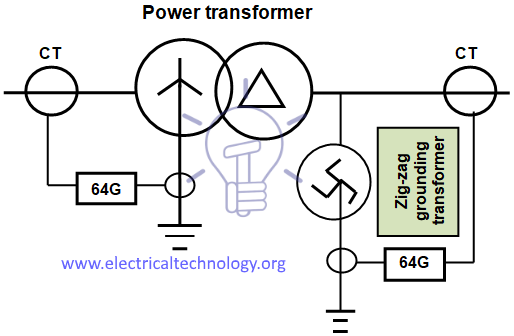
Figure 3 – Diagram of restricted earth fault protection
Whenever there is an unbalancing in between three phases of the power transformer, a resultant unbalance current flow through the close path connected to the common terminals of the CT secondary.
An unbalance current will also flow through the neutral of power transformer and hence there will be a secondary current in Neutral CT because of this unbalance neutral current.
In restricted earth fault scheme the common terminals of phase CT are connected to the secondary of Neutral CT in such a manner that secondary unbalance current of phase CT and the secondary current of Neutral CT will oppose each other.
If these both currents are equal in amplitude there will not be any resultant current circulate through the said close path. The restricted earth fault protection is connected in this close path. Hence the relay will not response even there is an unbalancing in phase current of the power transformer.
Overload Protection
The basic criterion for transformer loading is the temperature of the hottest spot of the solid insulation (hot-spot). It must not exceed the prescribed value, in order to avoid insulation faults, since loading capability of power transformers is limited mainly by winding temperature.
The temperature of solid insulation is the main factor of transformer ageing.
With temperature and time, the cellulose insulation undergoes a depolymerization process. As the cellulose chain gets shorter, the mechanical properties of paper such as tensile strength and elasticity degrade. Eventually the paper becomes brittle and is not capable of withstanding short circuit forces and even normal vibrations that are part of transformer life. This situation characterizes the end of life of the solid insulation. Since it is not reversible, it also defines the transformer end of life.
Transformer overloads can occur during contingency conditions that are the product of one, two, or various system elements being isolated from the power the system. They can also occur when transformers are already at 80%-90% of their full nameplate rating and extra capacity is needed, especially during hot summers.
Traditionally, inverse-time overcurrent relays (an inverse-time curve is characterized by the inverse variation of current with the time, as shown in Figure 4) for overload protection, but a difficulty is that transformers are usually outdoors where ambient temperature affects their loadability, and hence the optimum pickup settings of such relays.
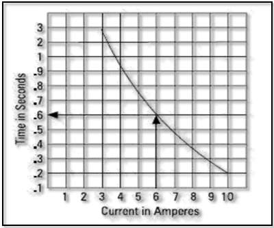 Figure 4 – Inverse-time characteristic curve
However, for liquid-immersed power transformers, the temperature of the winding hot-spot is the important factor in the long-term life of the transformer.
The insulating oil temperature is dependent on the winding temperature, and is used to indicate the operating conditions of the transformer. Many numerical transformer protection relays available today include protection functions that operate on insulating oil temperatures, calculated loss-of-life due to high oil temperature, and predicted oil temperatures due to load.
These types of functions are not routinely applied, but modern utility operating practices try to maximize the utilization of power transformers, which may increase the occurrence of over-temperature conditions and transformer ageing. Over-temperature conditions and accelerated aging are adverse system events that must be identified and protected against.
The most common function provided for thermal protection of power transformers is the thermal overload (ANSI/IEEE/IEC code 49) function.
The thermal capacity used is calculated according to a mathematical model which takes into account:
- Current rms values
- Ambient temperature
- Negative sequence current.
The protection gives a trip order when the heat rise E, calculated according to the measurement of an equivalent current Ieq, is greater than the set point Es.
The protection tripping time is set by the time constant T.
The thermal overload protection function may be used to protect equipment with two operating rates, for example transformers with two ventilation modes, with or without forced ventilation (ONAN / ONAF).
Lightning Protection
Lightning protection of power transformers is achieved by surge arresters installed in the transformer tank, as shown in Figure 5.
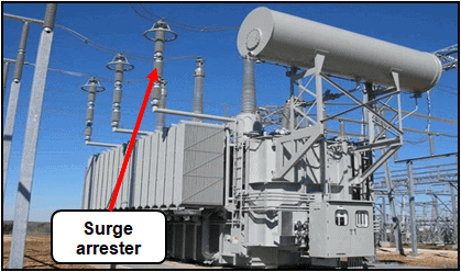 Figure 5 – Surge arrester
The most common surge arresters are non-linear metal oxide resistors type in porcelain or silicone rubber housing, and are fitted in parallel with the object protected and connected to the earth grid.
Resistance of non-linear resistors is in inverse proportion to the current, that is to say that the resistance is high for current service values and very low for high lightning discharge currents.
Transformers Fire Protection System
We have already discussed about it in detail in our previous post “Transformers Fire Protection System – Causes, Types & Requirements“.
![]()
Related Posts:
- Power Transformers Maintenance, Diagnostic & Monitoring
- Cables Feeder Protection – Faults Types, Causes & Differential Protection
- Motor Protection – Types of Faults and Protection Devices
- Generator Protection – Types of Faults & Protection Devices
- Overhead Lines Faults & Protection
- How To Locate Faults In Cables? Cable Faults, Types & Causes
- Fault Current Limiter and Their Types
- GFCI: Ground Fault Circuit Interrupter. Types, Working & Applications
- All About Electrical Protection Systems, Devices And Units


Excelente información teórica y muy práctica
How star and delta work.
Nice