How to Control Electric Water Heater using Switches?
Controlling of Water Heater using Single Pole, Two Poles & Intermediate Switches?
In our electric water heater wiring series, we will be showing that how to control the water heater using single way, two way, three way and four-way (intermediate) switches.

Controlling of Water Heater using Single-Pole Switch
To control a non-continuous (non-simultaneous) water heater using a single way or one-way switch, we must use a 10 gauge wire size with a minimum 30 amp circuit breaker. In our case, we have connected the water heater directly to a 30 amperes single way switch which is protected by a 30 amp circuit breaker from the main distribution board. The down position of the switch is used to break the line supply to the water heater. In the case of 240V heater, a single line cut off is sufficient to switch off the water heater. Also, don’t forget to do the proper grounding to the switch and water heater.
Click image to enlarge

Good to know:
- Always use 10 gauge wire for 240V, 30 amp circuit breaker according to the rating. 12 gauge can be used for single phase 120V according to the appliance rating.
- Use a minimum of 30A switch for 240V with 30A protection CB.
- A 240V breaker or switch can be used for 120V while, 120V rated breakers and switches can’t be used for 208, 240, 277 or 480V.
- Switch must be installed only and only on line (hot or phase) wire instead of neutral wire.
Controlling of Water Heater using Double Pole Switch
A double pole switch can be also used to control the ON/OFF operation of electric water heaters. In our case of 240V water heater, we have used a 30 amp double pole switch protected by a 30 amp circuit breaker form the main supply panel.
This way, both lines (hot or phase) wires are turned off by switch. Only breaking a single line supply will work perfectly, but we are still able to use the double pole switch instead of single pole switch as it makes sure to turn the power off to the water heater. This way, the double pole acts as a safety switch as well.
Safety switches are required in tankless water heaters, HVAC (heating, ventilation, and air conditioning), commercial water heaters or when the main circuit breaker box is not within sight.
Good to know:
- Always use the proper wiring diagram according to the user manual provided by the manufacturers.
- A 240V AC water heater element can be connected to the 120V AC.
- A 120V AC water heater element can’t be used for 240 or 230V.
Controlling of Water Heater using DPST Switch
The following wiring diagram shows a DPST (Double Pole, Single Throw) switch rated for 120V to 277V and fed-up by 240V 2-pole breaker is used to wire and control a water heater. It clearly shows the common (dark screws) are connected to the 240V supply voltage via Hot 1 and Hot 2. The L1 and L2 (brass screws are directly connected to the water heater. Since it is a 240V circuit, hence no Neutral is needed.
Click image to enlarge
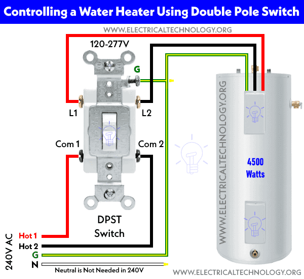
Finally, the ground wire is connected to both the DPST switch green screw and the terminal box of the water heater. This way, the ON and OFF operation will close or open both the sources i.e. Line 1 and Line 2.
Similarly, the following wiring diagram shows controlling of 240V non-continuous water heater thermostat and element using 20A double pole, single throw switch.
Click image to enlarge

Controlling of Water Heater from Two Places using Two, 3-Way Switches
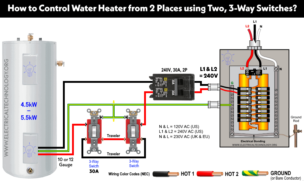
Using the following diagram, we can control an electric water heater from two different places, similar to the staircase wiring diagram where a single light bulb can be controlled from two places using three way switches.
In case of single phase 120V supply, the neutral is directly connected to the water heater where the hot wire (live or line) is connected to the common of a three way switch. Both 3-way switches are connected via traveler wires (blue) while the common of the second 3-way switch is connected to the water heater. A proper grounding and 30 A circuit breaker with 10 gauge wire should be used for 240V. In case of 120V, a 12 gauge wire should be used according to the rating. Only one live wire is enough to cut off the power supply through a 3-way switch. Overall, it is known as a 3-way circuit. Both switches and circuit breaker rating is 30 amperes.
Click image to enlarge
Good to know:
A switch rated for:
- 120V can only be used for 120V.
- 240V can be used for 120V, 240V but not for 277V (Commercial applications)
- 120-277 can be used for 120V, 240V and 277V.
Controlling of Water Heater from Three Places using Two, 3-Way & Four Way Switch
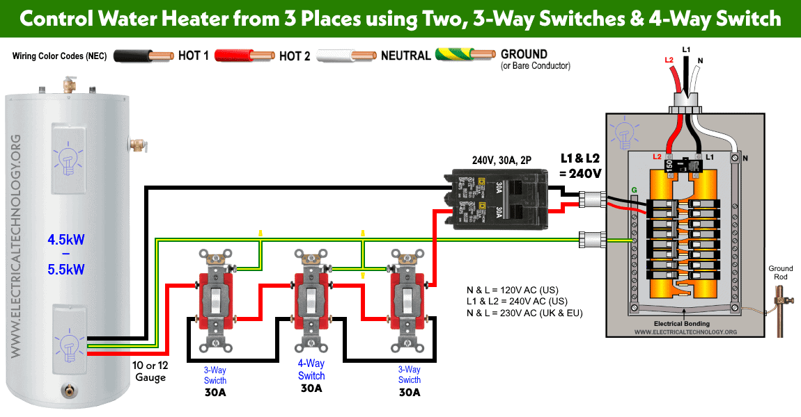
If we connect an intermediate (4-way) switch in between two 3-way switches in the above circuit, we will be able to ON/OFF the water heater from three different places as shown in below wiring diagram for 240V, 230V and 120V AC.
The rating of circuit breaker and all switches including three way and 4 way is 30 amp. You may use proper rated switches and breaker size for single phase 120V. Don’t forget to do proper earthing/grounding to the water heater and switches.
Click image to enlarge
Good to Know:
- A switch rated for 15A, 120V can be used on a 20A, 120V circuit.
- A switch rated for 20A, 120V can’t be used on household 15A, 120V circuits.
- A switch rated for 120V can’t be used on 240V circuits and vice versa.
- A 240V switch can be used on a 120V circuit if the ampere rating is the same.
- A 120V switch can’t be used on 240V circuit even if current rating in amperes are the same.
Precautions
Related Water Heater Wiring Diagrams


What is a thankless water heater?
Thanks to the auto correction. It was tankless – Instant water heater.
I think the adding switches for different control points is good but how can the individual know if the switch is in the on or off position or other words know if they turned the tank on or off with no indication at the switch as to whether power is flowing at 240v. and not in the off position with only 120v.flowing to the tank?
There needs to be an indicator light showing that both 120 v. lines are flowing to the tank.
I would not recommend this. If not installed with correct switches, you can start a fire. If you want to save money, Call a licensed electrician and install a U.L. listed time clock large enough to handle the load. I don’t want to say I told you so.
Non-contact safety interlock switches are extensively used across industries owing to its compactness and the non-contact way to interlock doors, guards, gates and etc.