Load Frequency Control (LFC) & Turbine Governor Control (TGC) in Power System
LFC and TGC in Power System – Load Frequency and Turbine Governor Control
Brief introduction to Thermal Generating Units
Generation of electricity is being done by both renewable and non-renewable energy resources. Thermal generating units are conventional method of electricity generation in which the fuel i.e. coal, nuclear energy, natural gas, biofuel, biogas etc. is burnt in a boiler.
Boiler of a generating unit is a extremely complex system but in the simplest form, it can be understood as a room whose walls are made with pipes in which there is a continuous flow of water. The thermal energy released by burning of fuel inside boiler is transferred to water. In this process, water converts into the dry saturated steam of high pressure (150ksc to 380ksc depending upon the design) and high temperature (530°C- 732°C depending upon the design).
Saturated steam is fed into the turbine where it expands and its temperature gets decreased, in this process steam transfers its thermal energy to the rotational energy of turbine shaft. The flow of steam into a turbine is regulated by the control valve which is controlled by the governing system of the turbine. Hence, the active power flow of the turbine is controlled by the governor. The turbine is coupled with a synchronous generator.
Synchronous generator converts the mechanical energy of turbine into the electrical energy. Synchronous generators generate power at lower voltages which ranges from 11kV to 26kV and nominal frequency. The voltage is stepped up to 220kV/400kV/765kV by a generating transformer for transmission to grid. This complete system is termed as a generating unit in power system studies.
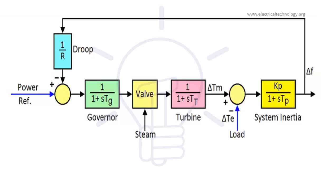
Turbine Governor Control (TGC)
As mentioned earlier, the governor regulates the flow of active power into the Turbine by controlling the control valve. A hydraulic governor can be modelled as integral controller which takes feedback from the actual speed of the turbine. Figure-1 shows the functioning of the governor in the speed control mode.

The actual speed of turbine is compared with the reference speed (corresponding to the nominal frequency) and the error signal (∆ωr) is then fed to the governor. Based on the error signal governor opens or closes the control valve position i.e. when a positive error signal is received it means actual frequency is more than nominal frequency, in this case, governors closes the valve a little bit and vice versa.
R is the droop setting of the governor and generally varies from 3%-8%.
R = pu change in frequency / pu change in power
Droop setting is required for stable parallel operation of various generating units and determines the load sharing in a control area. The unit with lesser droop value will share more load.
Control Area:
In a power system many generating units and loads are connected in distributed manner. To maintain the stability, the total grid is divided into various control areas primarily based on the geographical locations for effective load flow calculations and subsequent control of frequency and power balance. In a control area more than one generating units as well as loads are considered. Following objectives are achieved by dividing the power system into smaller control areas-
- Load frequency control: It also helps to maintain the frequency of grid by load frequency control methods. It is discussed in detail ahead.
- Determination of schedule interchanges: In a control area (geographical location), there is a possibility that the generation is less that the load demand, hence the power flows into this control area from nearby control areas by Tie Lines and vice versa.
- Effective load sharing: The load demand reduces in the night time and is at peak at evening time and morning time. By dividing the power system into smaller control areas, it becomes easy to determine load sharing by different units as per the projected load demand during a day in accordance with their capacity and for calculation of schedule interchanges with other control area.
Power Balance:
At any point of time, electrical energy produced must be consumed by all the connected loads as it cannot be stored. Electrical energy is a real-time energy. Hence, balance of power is always there in electrical system. This balance of power can be denoted as-
Power Generated (Pg) = Load demand(Pd) + Transmission losses(Pl)
Transmission losses are generally in the range of 2% of generated power, hence we will neglect them for understanding subject topic i.e. frequency control. Thus, we can say that –
Power Generated (Pg) ~ Load demand(Pd)
Frequency Variation:
In a grid, many industrial loads, house loads, lighting loads etc are connected. These loads are switched ON or OFF without any intimation. Hence, the load demand always fluctuates in a power system, whereas a generating unit is set to generate a particular power and can’t change generation very quickly as it is a mechanical system. Hence there are always minor gap between the demand and generation. Also, these minor deviations don’t result in the significant change in frequency due to the large inertia of power system.
However, when the demand-generation gap is significant then frequency may vary up to the range of ±5%. Significant demand-generation majorly occurs when-
- A generating unit is tripped (unplanned outage)
- A transmission line connecting a generating unit with the grid is tripped.
- A large load (in MWs) is switched on.
- A transmission line gets tripped catering to large industrial area load.
In first three instances, the load demand is higher than the generation resulting the significant dip in the frequency. In the 4th case, generated power is more than the demand, hence the demand generation gap is negative. In such cases frequency suddenly increases. Occurrence of frequency dip in the power system is more than that of frequency shoot and system responds exactly opposite in each scenario. Hence, by understanding the frequency dip scenario, we can simultaneously understand frequency shoot scenario.
The dip in the frequency occurs due to following two natural behaviours of the power systems-
- Load dampening – In the power systems major connected load is of induction motors. Be it a normal household fan or big industrial drives or traction loads. The power consumed by these loads is dependent on the frequency. Typically, 1 % frequency reduction corresponds to a 2% fall in active power consumption of induction loads in a large power system. Thus, when additional loads is switched on, the frequency reduces, in turn the power consumption by existing connected induction loads reduces to mitigate the demand generation gap.
- Supply of stored kinetic energy by TG sets- The conventional generating units use a turbine-generator set for generation of electrical power. Combined weight of turbine and generator rotor is more than 25 tonnes which rotates at 3000 RPM (in 50Hz grid). Thus, TG sets have high kinetic energy stored in their rotor. When the demand-generation gap is significant, active energy is momentarily supplied by the stored kinetic energy of rotors connected in the power system for up to 3-5 seconds depending upon the inertia constant of the rotors. By losing their stored kinetic energy, rotors slow down which results in immediate reduction in the grid frequency.
Frequency Control:
Load frequency control (or frequency control) is the system by which the frequency of the grid is kept or brought back to its nominal value after the demand-generation gap. The frequency control of the whole power system is done by generating units. There are two types of frequency controls viz. Primary frequency Control & Secondary frequency Control. Primary Control corresponds to the speed control mechanism of an individual unit, whereas secondary control is done by the co-ordinated control of various generating units located in different control areas.
Primary Frequency Control:
At unit level, frequency control is done through the governing system of the turbine. The speed control of the governing system has already been shown earlier. Each generating unit increases the steam input into the turbine by seeing the difference in the frequency. Complete primary frequency control loop of the generating station is shown in the figure below.
However, primary frequency control action will result in a steady state frequency deviation, depending upon the governor droop characteristic and frequency sensitivity of the load. This is because all individual units are running on speed control mode to increase the frequency irrespective to the location of addition of new load or how much load is added to the system. Without such assessment, it is impossible to bring power balance in the system and frequency deviation will persist. After primary frequency action by all the units steady state deviation in frequency may be positive or negative both.
Secondary Frequency Control
Restoration of system frequency to the nominal value requires secondary control action which actually sees the location of new load and adjusts the load reference set point of the selected few units.. Whenever the load increases in a particular control area, generation must be increased by generating units of the particular area so as to keep demand-generation balance at control area level and scheduled interchange between control areas in their pre-decided ranges.
For achieving this, few units in each control area are assigned for secondary control and in their control loop a frequency bias loop is added which gives the corrective signal for increase/decrease of generation based on the real-time load flow calculations. This is also known as Automatic Generation Control. After revised load set points are given to each units, they start to act to achieve their revised generation schedule. In individual units there is mechanical system for electrical power generation, hence it takes approx. 25-30 minutes to achieve the generation as scheduled by secondary control. After generating stations achieve the scheduled generation, power balance is once again reinstated and frequency comes to its nominal value.

The overall response of the system with the primary and secondary frequency control can be understood by the graph below.

A-B: The system was running at a power balance state prior to point-A. At point A, suddenly the load is increased from Po to Po + ∆P. There is a time delay of approx.3-5 seconds for the governor come into action. Hence, till that time, the stored kinetic energy of the rotor caters to excess load and in this process its speed gets slow and frequency decreases up to lowest point f1.
B-C: After about 5 seconds the governor starts speed control action and steam input starts to increase and the speed of the rotor is increased. This stage lasts about 20-25 seconds depending upon the dip of the frequency. But as mentioned earlier, there is always a steady state error ∆f in the frequency after primary control action.
C-D: After stabilization of frequency secondary frequency control actions starts and the selected generating units of each control areas increase or decreases their generation based on new load reference incorporating the frequency bias loop. This action may take several minutes as generating units have a Design ramp rate for reducing or increasing the load. After this action scheduled interchanges also come within the calculated value. Thus power system finds the new power balance and nominal frequency.
Related Posts:
- What Exactly Is A Smart Grid? Smart Grid Applications
- Internet of Things (IOT) and Its Applications
- Integration of Renewable Energy with Grid System
- Analysis of Reactive Power in Power System
- Analysis of a Simple R-L Circuit with AC and DC Supply
- Time Response of Second Order Transfer Function and Stability Analysis