Analysis of a Simple R-L Circuit with AC and DC Supply
Analysis of a Simple R-L Circuit and Inductor Behavior
Analysis of a Simple R-L Circuit with DC Supply:
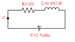
The circuit shown in Figures-1 is a simple R-L circuit (it has one simple resistor & inductor connected in series with a voltage supply of 2V); Though it is a simple circuit but if you will analyze it, your Electrical Engineering basics will be enhanced. First, we will analyze the circuit, when the DC voltage is applied. Can you find current in circuit-1; Answer is current I1=2 A. Its very simple, apply ohms law I=V/R; So, what is the role of an inductor in this circuit? Consider another circuit (Figure-2). Current in this circuit is also I2=2 A. So, you might be thinking again what is the role of the inductor?

Answer is:
- In steady state (i.e. when the system is settled), the inductor will behave as a short circuit (i.e. the voltage across the inductor is zero)
- When the circuit is started (at t=0+), inductor behaves as open circuit, so at that time current in the circuit is zero, it increases exponentially and reached to steady state.
- We can say, the inductor has a role in the transient period, but in steady state, it behaves as a short circuit (in DC supply).
- More will be the value of an inductor, more is the transient period (i.e. circuit will take more time to settled down)
- An inductor stores the energy ½LI2 . At the time of starting of a circuit, energy in the inductor is zero; slowly as the current rises, the inductor will store the energy (as you can understand ‘I’ is increasing, it means ½LI2 is increasing). Inductor will not dissipate any energy in the atmosphere (assuming that it is an ideal inductor).
- When it will store complete energy ½LI2 , it will become silent, the voltage across inductor will be zero.
- In Figure-3, various conditions, of circuit-1, at the time of starting of circuit (i.e. t=0+) is shown (you can understand in the starting of circuit as the current is zero, voltage across resistor is zero; as the time will pass, current will increase exponentially; voltage across resistor will exponentially increase, voltage across inductor will decrease exponentially).

- In Figure-4, various conditions, of circuit-1, in steady state are shown.
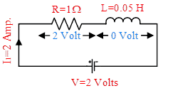
- In steady state, circuit-1 is consuming power 4 Watt (I2R). It means resistor is consuming 4 Joule energy per second and dissipating it into the air. In other words, we can say electrical energy is converted into thermal energy. If you will keep the finger near the resistor in hardware experiment, you will find it hot (please don’t touch it otherwise you will get shocked, just keep the finger near the resistor). While you are using any motor, transformer, etc., you will find that after some time they become hot. The reason is all the losses are dissipated in the air. (Suppose any motor has losses 4 KW, it means it is dissipating 4 KJ energy per second in the air)
- Inductor will store the energy, it will not dissipate any energy in the air. In circuit-1, energy stored by the inductor is 0.1 Joule.
- In Figure-5, rise in currents of circuit-1 & 2 are shown. It can be seen that transient period of circuit-1 is more. The reason is inductor has high value in circuit-1, so it will take more time to store the energy.

- Or, we can say time constant L/R, is more in circuit-1, hence it will take more time to reach a steady state.
- Transient period of circuit-1 is more, now, we will explain it through the control system.
Voltage equation of a simple R-L circuit (in case of DC) can be written as:
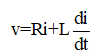
(You can understand, in steady state current ‘i’ is constant hence its derivative is zero, so in steady state relation V = RI is followed by both circuit-1 & 2).
In Laplace form this voltage equation can be written as:
![]()
[In Laplace form, derivative (i.e. differentiation) is represented as ‘s’ and integration is represented as ‘1/s’. In the time domain, quantities are represented in small letters such as current can be expressed as ‘i(t)’ or ‘i’. In Laplace domain quantities are represented in capital letters, for example, current can be expressed as ‘I(s)’].
Above equation can be written as:

The standard form of a first-order transfer function is

So, you can understand simple R-L circuit is an example of a first-order transfer function. L/R is the time constant (you can find that unit of L/R is second).
We have derived the transfer function of a simple R-L circuit through voltage equation in which DC is applied, but this transfer function is valid for any type of input (i.e. AC also).
Now for circuit-1, R=1Ω, L=0.05 H, hence transfer function is:
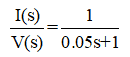
Its characteristics equation is ‘0.05s+1=0’; so its roots (poles of transfer function) is s=–20.
Now for circuit-2, R=1Ω, L=0.005 H, hence transfer function is:
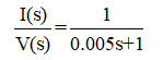
Its characteristics equation is ‘0.005s+1=0’; so its roots is s=–200.
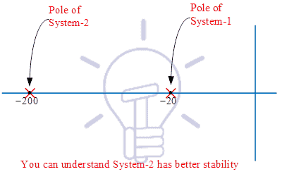
You can understand, both the systems are stable, but pole of circuit-1 is near to the imaginary axis (Figure-6), hence lower stability in comparison to circuit-2; due to this reason transient period of system-1 is more.
It was all about the important points of a simple R-L circuit.
Analysis of a Simple R-L Circuit with AC Supply
In the books of Electrical Engineering, you might have studied that
- In the R-L circuit if AC is applied current lags behind the voltage.
- In the R-C circuit if AC is applied current leads the voltage.
Reason of the first sentence, now you can understand. Suppose in the R-L circuit, AC is applied than inductor will behave as an open circuit in the starting. So, development of current requires some time, due to this reason, current lags behind the voltage in R-L, AC circuit.
In case of AC, in steady state, the inductor will offer reactance 2πfL; more will be the inductor value, more will be the transient period, and hence more the current will lag with respect to voltage.
In circuit-2, if AC is applied then, waveforms of input (voltage) and output (current) is shown in Figure-7

It can be seen that voltage and current, both are started from zero, but the development of current is slow, it is lagging from the starting, so it is lagging in the steady state also.
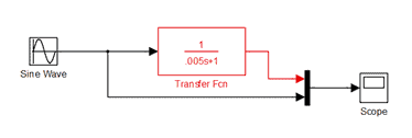
How the waveform of Figure-7 is generated? It is generated with the help of MATLAB, the diagram is shown in Figure-8. With the help of this Figure, you can also generate these waveforms.
If you want to generate a waveform of current, against DC voltage, apply the step input instead of the sine wave. As the DC voltage is 2V in circuit-2, hence keep final value is equal to 2 in step input block (also keep step time=0); you may get the waveform as per the Figure-5.
Analysis of an Inductor Behavior:
In the books of Electrical Engineering, you might have studied that
- Current through an inductor cannot change instantaneously,
- The voltage across a capacitor cannot change instantaneously.
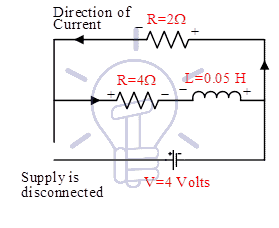
We will give you an explanation of the first sentence here, it may enhance your Electrical Engineering basics. Consider the circuit shown in Figure-9:
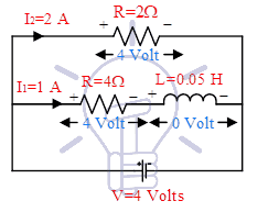
Values of current in steady state are I1=1A, I2=2A. Various polarities of voltages are shown. The voltage across the inductor is zero in steady state, but the polarity of voltage across the inductor is shown during the charging period. Suppose, the voltage source is disconnected, now what will happen?
In this case, the inductor will start discharging. Current through the inductor will decrease exponentially. The direction of current through inductor will remain the same, but voltage across inductor will change instantaneously. Current and voltage both will be reversed in 2Ω resistor immediately. Energy stored in the inductor will be dissipated in the air through I2R losses in both the resistors. Various conditions during discharging of the inductor is shown in Figure-10.
So, we hope, explanation of the sentence “Current through inductor cannot change instantaneously” may be clear to you. You can see voltage across inductor is changed instantaneously (it is reversed immediately), but current continue to flow in same direction and slowly decreased to zero. In the case of resistor, current and voltage both can be changed or reversed instantaneously.
Related Posts:


