Analysis of Reactive Power in Power System
Analysis of Reactive Power in Power System
Reactive power is an imaginary power, but still, it is needed in the Power System. If reactive power is in excess in Power System than voltage may go up and in case of shortage of reactive power voltage may be low. In this article, we will explain various aspects of reactive power, what its role is in Power System and how it can be injected into the Power System.
Basics of Voltage & Reactive Power in Power System:
It is desirable that the Voltage in Power System should be 1 per unit (pu) everywhere (but it is highly impossible to maintain it). Control of reactive power and magnitude of voltage is almost co-related words; similarly, control of active power and angle of voltage is almost co-related words. Consider Figure-1. Bus-1 is connected with infinite bus with a long transmission line. Generally, Active power flows from high voltage angle to lower voltage angle and reactive power flows from higher voltage magnitude to lower voltage magnitude. So, In Figure-1, Active & Reactive power both will flow from bus-1 to bus-2 (in few cases it depends on other factors also).
Analysis of Reactive Power in Synchronous Generator:
Consider a simple equivalent circuit of Synchronous Generator (SG) as shown in Figure-2. Its terminal voltage is 1∠0, or we can say that SG is directly connected to infinite bus.
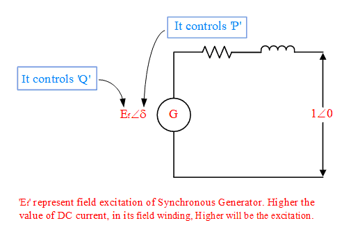
It should be noted that reactive power is imaginary power so it can be supplied or absorbed by SG. If Ef is less than ‘1’ (i.e. Ef<Vt), than we will say it is running at low excitation (i.e. DC current in its field winding is low); In that case, SG may consume reactive power. If Ef is more than ‘1’ (i.e. Ef>Vt), than we will say it is running at high excitation (i.e. DC current in its field winding is high); In that case, SG may supply reactive power.
Active power is called true power. SG always supplies active power; so, you can understand why rotor angle is plus in case of Synchronous generator and it is minus in case of Synchronous motor.
Equation “Input = output + losses” is valid for any machine. For SG, equation is “Mechanical Input = Electrical output (Active power) + losses”.
As written above, if SG is running at high excitation than it may generate reactive power, i.e. SG will supply the reactive power to the system. In fact, what’s happen, it is just an energy exchange between generator & load. (Suppose the load is Induction Motor. So, there will be an energy exchange between SG & Induction Motor; or we can say SG is generating reactive power and Induction Motor is consuming the reactive power; but it is just conventions, reactive power is imaginary power hence cannot be generated or consumed).
In the books of Power System, to calculate complex power, formula S=VI* is mentioned. If formula S=V*I is used than the same result can be found except that sign of reactive power will be reversed. So, Electrical Engineering Scholars have finalized the formula S=VI* and discarded the second formula. Why they have chosen first formula instead of second, try to analyze yourself on the basis of this article.
From the Figure-3, you can easily understand, why active power is called true power and reactive power is called imaginary power.

One diagram of SG is shown in Figure-4. This Figure is also self-explanatory.
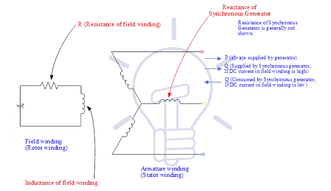
In its field finding if DC voltage (or DC current) is high than SG will supply more reactive power. So, perhaps you may think DC power of field winding is converted into reactive power. It is a big misconception among students. Please note, More DC voltage in field winding means more DC current, and this power will be consumed as I2R losses in the field winding resistance ‘R’. No DC power in the field circuit will be converted into reactive power. As the DC current increases, than reactive power supplied by SG increases, it means the energy exchange of generator is increased with the load. In case of high DC current in field winding, the flux in inductance of field winding will be high, it will help to generate reactive power by SG.
Consider Figure-1 again. If excitation of SG is increased than two things will happen
- (i) Generator will supply more reactive power
- (ii) its terminal voltage (magnitude) will increase (as said earlier control of reactive power and magnitude of voltage is almost co-related words).
If there is an excess of reactive power in the power system than voltage increases, it is vice versa. On that basis, readers should try to understand the Ferranti effect also. [In case of Ferranti effect, receiving end voltage is higher than sending end voltage. It occurs at no load (or load is very less). Most of the load in the power system is an inductive load. So, in no-load conditions inductive effect decreases and shunt capacitance (natural shunt capacitances in the air) dominates. Capacitor generates reactive power hence it tries to increase the voltage]
In the books of Electrical Machines, it is written that at leading PF load (i.e. at capacitive load), a transformer may have negative voltage regulation; Readers should try to understand this line also with the help of this article. Note that the capacitive load tries to increase the voltage. Suppose you have a transformer of turns ratio 1:1, the applied voltage is 100 V, it’s terminal voltage is 102 V, then the voltage regulation of transformer, is simply -2%. It is possible in case of capacitive load. Fresher’s may be surprised how terminal voltage of transformer may be more than applied voltage, they should try to analyze it.
Shunt Compensation and Series Compensation:
Two terms ‘Shunt compensation’ and ‘Series compensation’ are commonly used in Power System. ‘Shunt compensation’ controls reactive power and ‘Series compensation’ controls active power. Shunt compensation may be a simple capacitor in the shunt of the transmission line or any Shunt FACTS devices. Series compensation may be a simple capacitor in series with the transmission line or any series of FACTS devices.
Consider formula 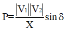 (It is a very famous formula, hence no detail explanation is given here). ‘X’ is the reactance of the transmission line. This formula is derived, assuming that resistance of transmission line is negligible. If a simple series capacitor is inserted into the transmission line (or between the bus-1 and bus-2 in Figure-1), then we can say it is series compensation. By controlling the value of the series capacitor, we can control the ‘X’, hence ‘P’ can be controlled. Also, you can see ‘P’ is related to ‘δ’. (As written earlier control of ‘P’ and ‘voltage angle’ are closely related words).
Methods of Injecting Reactive Power in Power System:
If the voltage in Transmission System is less than 1 pu, then reactive power should be injected into the system. Various Methods of Injecting/absorbing Reactive Power in Power System are given below:
- Control of DC excitation of SG, as explained above in this article,
- Shunt capacitors (To supply reactive power & to increase the voltage),
- Shunt inductors (To consume the reactive power & to bring down the voltage), in case of Ferranti effect (i.e. when the load is very less and receiving end voltage may be high), it is used.
- TCR-FC or TCR-TSC (It is an impedance-based FACTS devices),
- STATCOM (It is a Voltage Source converter based FACTS devices). STATCOM or Static Synchronous Compensator is a power electronic device using force commutated devices like IGBT, GTO etc. to control the reactive power flow through a power network and thereby increasing the stability of power network. STATCOM is a shunt FACTS controller i.e. it is connected in shunt with the line. In initial days its name was STATCON instead of STATCOM. It is a member of the Flexible AC Transmission System (FACTS) family of devices and have lot of research potential. Installing a STATCOM at one or more suitable points in a grid will enhance voltage stability and maintaining a smooth voltage profile under different network conditions. Its ability to perform active filtering is also very useful for improvements in power quality.
- In Wind farms, Induction Generator is used, it is a singly excited machine (i.e. it has no field winding). So, reactive power control in an Induction Generator is not possible; therefore, in this case, to supply reactive power, STATCOM is widely used. STATCOM is installed at the terminals of Induction Generator as a shunt controller. This topic also has large research potential.
Related Post: What is Shunt Reactor – Types, Construction & Applications
As written in this article ‘shunt compensation’ is related to reactive power control, it can be seen that in the above methods from 2-6, all are the shunt controllers.
As said earlier reactive power is imaginary power, so transmission lines are meant to supply active power. It is a question why we are injecting reactive power into the Power System. The answer is, generators, transmission lines, transformers etc., have negligible resistance as compared to their inductive reactance, so we can say transmission system is an inductive circuit. It is consuming reactive power, hence to compensate it we have to supply reactive power.
In other words, we can say, to maintain flat voltage profile (i.e. to maintain voltage 1 pu everywhere), in a transmission system, proper reactive power control is necessary. To avoid excessive reactive power transmission; generation and consumption of reactive power should be as close as possible to each other; otherwise, it will result in inappropriate voltage profile.
Related Post:


