How to Design and Install a Solar PV System?
Design and installation of Solar PV Systems
Today our modern world needs energy for various day to day applications such as industrial manufacturing, heating, transport, agricultural, lightning applications, etc. Most of our energy need is usually satisfied by non-renewable sources of energy such as coal, crude oil, natural gas, etc. But the utilization of such resources has caused a heavy impact on our environment.
Also, this form of energy resource is not uniformly distributed on the earth. There is an uncertainty of market prices such as in the case of crude oil as it depends on production and extraction from its reserves. Due to the limited availability of non-renewable sources, the demand for renewable sources has grown in recent years.
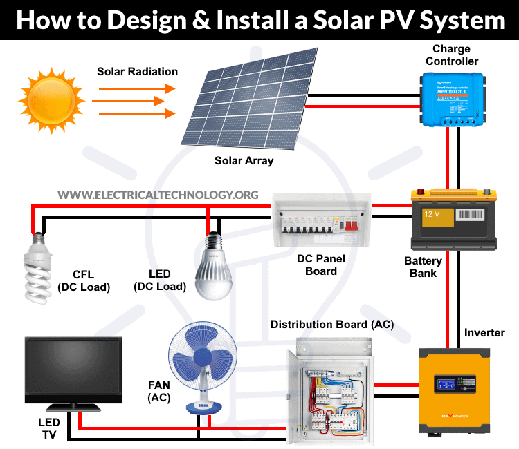
Solar energy has been at the center of attention when it comes to renewable energy sources. It is readily available in an abundant form and has the potential to meet our entire planet’s energy requirement. The solar standalone PV system as shown in fig 1 is one of the approaches when it comes to fulfilling our energy demand independent of the utility. Hence in the following, we will see briefly the planning, designing, and installation of a standalone PV system for electricity generation.
- Related Post: A Complete Guide About Solar Panel Installation. Step by Step Procedure with Calculation & Diagrams
Planning of a Standalone PV system
Site assessment, surveying & solar energy resource assessment:
Since the output generated by the PV system varies significantly depending on the time and geographical location it becomes of utmost importance to have an appropriate selection of the site for the standalone PV installation. Thus, the following points must be considered for the assessment and selection of locations for installation.
- Minimum Shade: It must be made sure that the selected site either at rooftop or ground should not have shades or should not have any structure that intercepts the solar radiation falling on the panels to be installed. Also, make sure that there won’t be any structural construction soon surrounding the installation that might cause the problem of shading.
- Surface Area: The surface area of the site at which the PV installation is intended should be known, to have an estimation of the size and number of panels required to generate the required power output for the load. This also helps to plan the installation of inverter, converts, and battery banks.
- Rooftop: In the case of the rooftop installation the type of roof and its structure must be known. In the case of tilt roofs, the angle of tilt must be known and necessary mounting must be used to make the panels have more incidents of solar radiation i.e. ideally the radiation angle must be perpendicular to the PV panel and practically as close as to 90 degrees.
- Routes: Possible routes for the cables from an inverter, battery bank, charge controller, and PV array must be planned in a way that would have minimum utilization of cables and lower voltage drop in cables. The designer should choose between the efficiency and the cost of the system.
To estimate the output power the solar energy assessment of the selected site is of foremost significance. Insolation is defined as the measure of the sun’s energy received in a specified area over a period of time. You can find this data using a pyranometer, however, it is not necessary as you can find the insolation data at your nearest meteorological station. While assessing the solar energy the data can be measured in two ways as follows:
- Kilowatt-hours per square meter per day (KWh/m2/day): It is a quantity of energy measured in kilowatt-hours, falling on square meter per day.
- Daily Peak Sun Hours (PSH): Number of hours in a day during which irradiance averages to 1000 W/m2.
Peak sun hours are most commonly used as they simplify the calculations. Do not get confused with the “Mean Sunshine Hours” and “Peak Sun Hours” which you would collect from the meteorological station. The “Mean sunshine hours” indicates the number of hours the sunshine’s were as the “Peak sun hours” is the actual amount of energy received in KWh/m2/day. Amongst all months over a period of year use the lowest mean daily insolation value as it will make sure that the system will operate in a more reliable way when the sun is least due to unsuitable weather conditions.
Considerations for Standalone PV system
Calculation of Energy Demand
The size of the standalone PV system depends on the load demand. The load and its operating time vary for different appliances, therefore special care must be taken during energy demand calculations. The energy consumption of the load can be determined by multiplying the power rating (W) of the load by its number of hours of operation. Thus, the unit can be written as watt × hour or simply Wh.
Energy demand Watt-hour = Power rating in Watt × Duration of operation in hours.
Thus, the daily total energy demand in Wh is calculated by adding the individual load demand of each appliance per day.
Total energy demand Watt-hour = ∑ (Power rating in Watt × Duration of operation in hours).
A system should be designed for the worst-case scenario i.e. for the day when the energy demand is highest. A system designed for the highest demand will ensure that the system is reliable. If the system meets the peak load demand it will meet the lowest demand. But designing the system for the highest demand will increase the overall cost of the system. On the other hand, the system will be fully utilized only during the peak load demand. So, we have to choose between cost and reliability of the system.
Inverter & Converter (Charge Controller) Ratings
For choosing the proper inverter both the input and output voltage and current rating should be specified. The inverter’s output voltage is specified by the system load, it should be able to handle the load current and the current taken from the battery bank. Based on the total connected load to the system the inverter power rating can be specified.
Let’s consider 2.5 kVA in our case, hence an inverter with power handling capacity having a size of 20-30% higher than the power running the load should be chosen from the market. In the case of motor load, it should be 3-5 times higher than the power demand of such an appliance. In the case of the converter, the charge controller is rated in current and voltage. Its current rating is calculated by using the short-circuit current rating of the PV module. The value of voltage is the same as the nominal voltage of batteries.
Converter and Charge Controller Sizing
The charge controller rating should be 125% of the photovoltaic panel short circuit current. In other words, It should be 25% greater than the short circuit current of solar panel.
Size of solar charge controller in amperes = Short-circuit current of PV × 1.25 (Safety factor).
For example, we need a 6 numbers each of 160W solar panels for our system. Following are the related date of PV panel.
Suppose the PV module specification are as follow.
- PM = 160 WPeak
- VM = 17.9 VDC
- IM = 8.9 A
- VOC = 21.4 A
- ISC = 10 A
The required rating of solar charge controller is = (4 panels x 10 A) x 1.25 = 50 A
Now, a 50A charge controller is needed for the 12V DC system configuration.
Note: This formula is not applicable on MPPT Solar chargers. Please refer to the user manual or check the nameplate data rating for proper sizing.
Inverter Sizing
The size of Inverter should be 25% bigger than the total load due to losses and efficiency problem in the inverter. In other words, It should be rated 125% than the total load required in watts. For example, if the required wattage is 2400W, than the size of inverter should be:
2400W x 125%
2400W x 1.25
3000 Watts.
So we need a 3kW of inverter in case of 2400W load.
Daily Energy Supplied to Inverter
Let us consider in our case the daily energy consumption by the load is 2700 Wh. Note that the inverter has its efficiency, thus the energy supplied to the inverter should be more than the energy used by the load, so the losses in the inverter can be compensated. Assuming 90% efficiency in our case, the total energy supplied by the battery to the inverter would be given as;
Energy supplied by the battery to the inverter input = 2700 / 0.90 = 3000 Wh/per day.
System Voltage
The inverter input voltage is referred to as the system voltage. It is also the overall battery pack voltage. This system voltage is decided by the selected individual battery voltage, line current, maximum allowable voltage drop, and power loss in the cable. Usually, the voltage of the batteries is 12 V so will be the system voltage. But if we need higher voltage it should be multiples of 12 V. i.e. 12 V, 24 V, 36 V, and so on.
By decreasing the current, power loss and voltage drop in the cable can be reduced, this can be done by increasing the system voltage. This will increase the number of batteries in the series. Therefore, one must choose between power loss and system voltage. Now for our case let us consider the system voltage of 24 V.
Sizing of the Batteries
While sizing the battery some parameters are needed to be considered as follows:
- Depth of Discharge (DOD) of the battery.
- Voltage and ampere-hour (Ah) capacity of the battery.
- The number of days of autonomy (It is the number of days required to power up the whole system (backup power) without solar panels in case of full shading or rainy days. We will cover this part in our upcoming article) to get the needed Ah capacity of batteries.
Let us consider we have batteries of 12 V, 100 Ah with DOD of 70%. Thus, the usable capacity of the is 100 Ah × 0.70 = 70 Ah. Therefore, the charged capacity that is required is determined as follows;
Required charge capacity = energy supplied by the battery to the inverter input/system voltage
Required charge capacity = 3000 Wh/ 24 V = 125 Ah
From this, the number of batteries required can be calculated as;
No. of batteries required = Required charge capacity / (100 × 0.7)
No. of batteries required = 125 Ah / (100 × 0.7) = 1.78 (round off 2 batteries)
Thus, 2 batteries of 12 V, 100 Ah are required. But due to round off 140 Ah instead of 125 Ah is required.
Required charge capacity = 2 × 100Ah × 0.7 = 140 Ah
Therefore, two 12 V, 100 Ah batteries in parallel to meet the above charge capacity. But as the individual battery is of 12 V, 100 Ah only and the system voltage requirement is of 24 V we need to connect two batteries in series to get the system voltage of 24 V as shown in figure 2 below:

So, in total there will be four batteries of 12 V, 100 Ah. Two connected in series and two connected in parallel.
Also, the required capacity of batteries can be found by the following formula.

Sizing of the PV Array
Different sizes of PV modules available in the market produce a different level of output power. One of the most common way to determine the sizing of the PV array is to use the lowest mean daily insolation (Solar irradiance) in peak sun hours as follows;
The total size of PV array (W) = (Energy demand per day of a load (Wh) / TPH) × 1.25
Where TPH is the lowest daily average peak sun hours of a month per year & 1.25 is the scaling factor. With this the number of PV modules Nmodules required can be determined as;
Nmodules = Total size of the PV array (W) / Rating of selected panels in peak-watts.
Suppose, in our case the load is 3000 Wh/per day. To know the needed total WPeak of a solar panel capacity, we use PFG factor i.e.
Total WPeak of PV panel capacity = 3000 / 3.2 (PFG)
= 931 WPeak
Now, the required number of PV panels are = 931 / 160W = 5.8.
This way, we need 6 numbers of solar panels each rated for 160W. You can find the exact number of solar panels by dividing the WPeak by other rating i.e. 100W, 120W 150W etc based on the availability.
Note: The value of PFG (Panel Generation Factor) is varying (due to climate and temperature changes) in different regions e.g, PFG in USA = 3.22, EU = 293, Thailand = 3.43 etc.
Moreover, the additional losses should be considered to find the exact panel generation factor (PGF). These losses (in %) occur due to :
- Sunlight not striking the solar panel straight on (5%)
- Not receiving energy at the maximum power point (excluded in case of MPPT charge controller). (10%)
- Dirt on solar panels (5%)
- PV panels aging and below specification (10%)
- Temperature above 25°C (15%)
Related Post Types of Solar Panels and Which Solar Panel Type is Best?
Sizing of the Cables
The sizing of the cables depends on many factors such as maximum current carrying capacity. It should have a minimum voltage drop and have minimum resistive losses. As the cables would be placed in the outdoor environment it should be water-resistant and ultraviolet.
The cable must behave minimum voltage drop typically less than 2% as there is an issue of voltage drop in low voltage system. Under sizing of the cables will result in energy loss and sometimes can even lead to accidents. whereas the oversizing is not economically affordable. The cross-sectional area of the cable is given as;
A = (ρIML / VD) × 2
Where
- ρ is the resistivity of the conducting wire material (ohm-meters).
- L is the length of cable.
- VD is the maximum permissible voltage drop.
- IM is the maximum current carried by the cable.
In addition, you may use this cable and wire size calculator. Also, use the proper sized circuit breaker and rated plugs and switches.
Lets have a solved example for the above example.
Example:
Suppose we have the following electrical load in watts where we need a 12V, 120W solar panel system design and installation.
- An LED lamp of 40W for 12 Hours per day.
- A refrigerator of 80W for 8 Hours per day.
- A DC Fan of 60W for 6 Hours per day.
Now let’s find the number of solar panels, rating and sizing of charge controller, inverter and batteries etc.
Finding the Total Load
Total Load in Wh / day
= (40W x 12 hours) + (80W x 8 hours) + (60W x 6 hours)
= 1480 Wh / per day
The required wattage by Solar Panels System
= 1480 Wh x 1.3 … (1.3 is the factor used for energy lost in the system)
= 1924 Wh/day
Finding the Size and No. of Solar Panels
WPeak Capacity of Solar Panel
= 1924 Wh /3.2
= 601.25 WPeak
Required No of Solar Panels
= 601.25 / 120W
No of Solar Panels = 5 Solar Panel Modules
This way, the 5 solar panels each of 120W will capable to power up our load requirements.
Find the Rating and Size of Inverter
As there is only AC loads in our system for specific time (i.e. no additional & direct DC load connected to the batteries) and our total required wattage is:
= 40W + 80W + 60W
= 180W
Now, the rating of inverter should be 25% greater than the total load due to losses in the inverter.
= 180W x 2.5
Inverter Rating & Size = 225 W
Related Posts:
- Series Connection of Solar Panel with Auto UPS System
- Parallel Connection of Batteries with Solar Panel
Find the Size, Rating & No of Batteries
Our load wattage and operational time in hours
= (40W x 12 hours) + (80W x 8 hours) + (60W x 6 hours)
Nominal Voltage of Deep Cycle Battery = 12V
Required Days of Autonomy (Power by batteries without solar panel power) = 2 days.
[(40W x 12 hours) + (80W x 8 hours) + (60W x 6 hours) / (0.85 x 0.6 x 12V)] x 2 days

The required capacity of batteries in Ampere-hour = 483.6 Ah
This way, we need a 12V 500Ah battery capacity for 2 days of autonomy.
In this case, we may use 4 number of batteries each of 12 V, 125Ah connected in parallel.
If the available battery capacity is 175Ah, 12 V, we may use 3 number of batteries. You can get the exact number of batteries by dividing the required capacity of batteries in Ampere-hour by the available battery Ah rating.
Required Number of batteries = Required capacity of batteries in Ampere-hour / Available battery Ah rating
- Related Post: Charging Time and Charging Current formula for Batteries (With Example of 120Ah Battery)
Find The Rating and Size of Solar Charge Controller
The charge controller should be 125% (or 25% greater) than the solar panel short circuit current.
Size of solar charge controller in Amp = Short circuit current of PV × 1.25
PV module specification
- PM = 120 WPeak
- VM = 15.9 VDC
- IM = 7.5 A
- VOC = 19.4 A
- ISC = 8.8 A
The required rating of solar charge controller is = (5 panels x 8.8 A) x 1.25 = 44 A
So you can use the next nearest rated charge controller which is 45A.
Note that this method can’t be used to find the exact size of MPPT solar chargers. Please refer to the user manual provided by the manufacturer or see the nameplate rating printed on it.
Finding the Cable, CB, Switches & Plug Ampacity
Use the following tools and explanatory posts with charts to find the exact amperage rating of wire and cables, switches & plugs and circuit breakers.
- Cable Wire Size Calculator or How to Find the proper wire size with ampacity.
- Find the Amperage rating of Switches & Plugs
- Find the Appropriate size and rating of circuit breaker.
Conclusion
The standalone PV system is an excellent way to utilize the readily available eco-friendly energy of the sun. Its design and installation are convenient and reliable for small, medium, and large-scale energy requirements. Such a system makes the availability of electricity almost anywhere in the world, especially in remote areas. It makes the energy consumer independent of the utility and other sources of energy such as coal, natural gas, etc.
Such a system can have no negative impact on our environment and can provide energy for long periods after its installation. The above systematic design and installation provide useful guidelines for our need for clean and sustainable energy in the modern world.
- By: M. Phansopkar
- Updated By: Electrical Technology
Related Posts:


I like to receive notifications on new article
Thank you. You can subscribe to our mailing list. This way, You will receive the new articles notifications in your inbox.
Great article. Planning on doing solar on my house.
Nice Blog
Design and installing step are complicated but you have described it in simple language.
The information was much helpful. I’m interested in starting a business in solar energy installation.
Yes interested ,thank you
I would like to receive notifications on new articles
I would like to receive these solar system articles. As I want to learn more about Solar
Can this article be downloaded in word or PDF format?
It takes discipline and natural goodwill to actually present this information on solar pv design without resorting to tools that act like blackboxes. Thanks.
Can this information be uploaded in PDF. An informative DIY on Solar Energy Installation.