How to Wire Lights in Parallel?
How to Connect Light Points in Parallel ?
The common household circuits used in electrical wiring installations are (and should be) arranged in parallel. Typically, switches, outlet receptacles, and lighting points, etc., are connected in parallel to ensure a continuous power supply to other electrical devices and appliances through the hot and neutral wires in case one of them fails. In this case, only the faulty load point will be disconnected and the rest of the circuits will work fine.
In today’s basic electrical wiring tutorial, we will demonstrate how to wire lights in parallel.

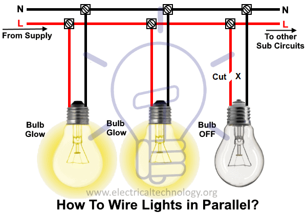
In the above fig, it is clearly shows that all the light bulbs are connected in parallel i.e. each bulb connected through separate Line (also known as Live or Phase) and Neutral wire.
In parallel circuit, adding or removing one lamp from the circuit has no effect on the others lamps or connected devices and appliances because the voltage in parallel circuit is same at each point but the flowing current is different. Any number of lighting points or load can be added (according to the circuit or sub-circuit load calculation) in this kind of circuit by simply extending the L and N conductors to other lamps.
As each lamp or Bulb is connected between Line L and Neutral N separately, if one of the light bulb gets faulty, the rest of the circuit will work smoothly as shown in fig below. Here, you can see there is a cut in the line wire connected to lamp 3, so the bulb is switch OFF and the rest circuit is working properly i.e. bulbs are glowing.
Also, if we control each lamp by single way (SPST=Single Pole Single Through) switch in parallel lighting circuit, We will be able to switch ON / OFF each bulb from from separate switch or if we switch OFF a bulb, the rest lighting points won’t affected as is it happens only in series lighting connection where all the connected load would be disconnected if we close the switch.

How to Control Light Bulb from Single Way Switch in Parallel Lighting?
In below fig, We have controlled three light bulbs from three separate single way switches connected in between line and neutral wires. The first two bulbs are glowing as the switches are at ON position while the third one bulb is switched OFF.

Advantages of Parallel Lighting Circuit:
- Each connected electrical device and appliance are independent from others. This way, switching ON / OFF a device won’t affect the other appliances and their operation.
- In case of break in the cable or removal of any lamp will not break the all circuits and connected loads, in other words, other lights/lamps and electrical appliances will still work smoothly.
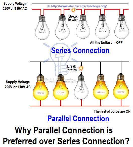
- If more lamps are added in the parallel lighting circuits, they will not be reduced in brightness (as it happens only in series lightning circuits). Because voltage is same at each point in a parallel circuit. In short, they get the same voltage as the source voltage.
- It is possible to add more light fixture and load points in parallel circuits according to future need as far as the circuit is not overloaded.
- Adding additional devices and components wont increase the resistance but will decrease the overall resistance of the circuit especially when high current rating devices are used such as air conditioner and electric heaters.
- parallel wiring is more reliable, safe and simple to use.

Disadvantages:
- More size of cable and wire is used in parallel lighting wiring circuit.
- More current needed when additional light bulb added in the parallel circuit.
- Battery runs out quicker for DC installation.
- The parallel wiring design is more complex as compare to series wiring.
Good to know:
- Switches and fuses must be connected through line (Live) wire.
- Connecting electrical devices and appliances like fan, outlet, light bulbs etc. in parallel is a prefer way instead of series wiring.
- Parallel or series-parallel wiring method is more reliable instead of series wiring.
Related basic home electrical wiring installation tutorials:
- How To Wire Switches In Series?
- How To Wire Switches in Parallel?
- How To wire Lamps in Series?
- What is the Objection to have Light Bulbs & Lamps Connected in Series?
- Introduction to Series, Parallel and Series-Parallel Connections
- Series, Parallel and Series-Parallel Connection of Batteries
- Difference Between Series and Parallel Circuit – Comparison


Thanks for your appreciation,
Nice post. This the normal and efficient electrical wiring in the houses. The most commonly used wire is copper coated with the PVC. Copper is used because of the best electricity conducting behavior. Nearly all large cities and smaller ones now follow the recommendations of the National Electrical Code. Electrical wiring is generally done by the experienced and certified electrical contractors
I have two garage door openers running off the same supply voltage. i currently have an external outside light the is wired to one of the garage door opener’s relay. When that garage door opener (GDO) ii’s activated, the external light comes on and stays on until the GDO lights shut off. Very convenient. I now want to use the same external light but with the other GDO. I am worried that if I wire the second GDO’ relay to the same light and both GDOs are activated at the same time, there will be two (2) 120 VAC feeding the light at the same time.
Is this a problem?
Thanks for the tips! I’ve been meaning to learn how to do this!
Nice post! It explains well these fundamental concepts. Just one observation: this statement
“As more lamps are added, they will all be reduced in brightness. Because voltages is shared or divided in a series circuit.”
It is the current that is divided in parallel wiring and not voltage. Otherwise nice piece of reading
Very good article for easily understand.
nice