Difference Between Series and Parallel Circuit – Comparison
Key Differences between Series and Parallel Circuits
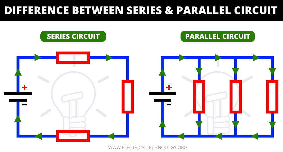
In electrical and electronics engineering it is very important to know the differences between series and parallel circuits. They are the two most basic forms of electrical circuit and the other one being the series-parallel circuit, which is the combination of both, can be understood by applying the same rules.
Before going into their differences, first, we are going to discuss what electrical circuit is and what are the major components of an Electrical circuit.
Electrical Circuit
An electrical circuit or network is a closed loop that provides a closed path to the flow of current. It is a pathway that connects different electrical components (such as power source, resistor, capacitors and inductor, etc.) together. It starts and ends at the same point forming a loop-like structure. A circuit has 3 major components; a power source, Electrical components (Load) and conductors (wires) for connection between them.

The power source is what energizes the circuit and allows the supply of current to the circuit. A power source can be a voltage source or a current source. A common example of a voltage source is a battery.
The Electrical components generally resistors, capacitors and inductors, etc. are the load connected to the power source. Using different types of electrical components affects the properties of the circuit.
The wires are pure conductors and they connect the electrical components and the power source together. Connecting the components in various configurations also varies the circuit properties such as Series, Parallel and Serial-Parallel Circuit.
The main two types of circuits are the Series and Parallel circuit. But before going into series and parallel circuit, let’s look into what a series and parallel Connection is.
Series Connection
A series connection between components is when two or more than two components are connected together in a cascaded form or the tail of the 1st component is connected to the head of the 2nd component and so on. Series connected components form a chain-like structure in a single line.

Parallel Connection
A connection is said to be parallel if two or more than two components are connected together side by side or their heads are connected together and their tails are connected together. The parallel-connected components form multiple paths or loops.

Series Circuit
A circuit is said to be a series circuit if the components are connected in a series configuration or cascaded formation in a single line. A series circuit forms a pathway that has only one loop, therefore, the current flowing through components is the same and the voltage divides depending on the resistance of each component.
- Related Post: How To Wire Lights in Series?

Current in Series Circuit
The current through each component in a series circuit remains the same and it is equal to the current supplied by the power source. Since there is only one path for the current flow, the current does no divide.
IT = I1 += I2 = I3 + … In

Voltage in Series Circuit
The sum of the voltage drops across each component in a series circuit is equal to the supply voltage. The voltage is a series circuit divides among the components based on their resistance. Therefore, the voltage drop across each component is different and depends on the value of resistance of the components.
VT = V1 + V2 + V3 + … Vn
Resistance in Series Circuit:
When resistors are connected in a series configuration their total resistance adds up and it is the sum of individual resistance of each resistor.
Req = R1 + R2 + R3 + … Rn
The total resistance in a series circuit is always greater than its individual resistance.
- Related Post: How To Wire Switches In Series?
Capacitor in a Series Circuit:
When capacitors are connected in series their total or equivalent capacitance decreases because the voltage difference across each capacitor decreases and the charge stored due to this voltage also decreases.
1/Ceq = 1/C1 + 1/C2 + 1/C3 + … 1/Cn
The total capacitance in a series circuit is always less than the individual capacitance.
Inductor is Series Circuit:
The total inductance of two or more than two inductors in a series circuit is the sum of individual inductance.
Leq = L1 + L2 + L3 + … Ln
The total inductance increases and it is always greater than the individual inductance in a series circuit.
Fault in Series Circuit:
If there is a fault in any component in a series circuit, the whole circuit does not work because the current flow breaks and there is no other path for the current to flow. So a fault in a single component will cause the whole circuit to deactivate. In order to troubleshoot a series circuit, you have to check each component. Thus, the troubleshooting series circuit is difficult than a parallel circuit.
A common example of the series circuit would be the Christmas lights, they are connected in series. If one of them stops working, the whole string does not light up and it is very difficult to spot the defective light.
Power Supplies in Series Circuit:
If two or more than two power supplies are connected in series their total or equivalent voltage will be the sum of individual voltages while the total current supplied will remain the same as the current supplied by individual supply.
You may use the following electrical formulas to calculate the power in a series circuit:
P = I2R1 + I2R2 + … I2Rn
or
P = V12/R1 + V22/R2 + … Vn2/Rn
So if you want to increase the voltage of power supply connected then in series. For example, two 6v batteries connected in series will provide 12V of the total voltage.
Parallel Circuit
A circuit is said to be a parallel circuit if the electrical components are connected in a parallel configuration or their end are connected to a common point. It forms multiple loops or pathways for the current to flow.

Current in Parallel Circuit
The current in a parallel circuit divides and branches through each pathway. There the total current or supply current is equal to the sum of the currents through individual components and it depends on the value of their resistance.
IT = I1 + I2 + I3 + … In
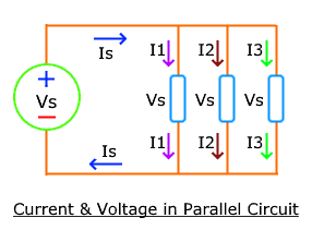
Voltage in Parallel Circuit
The voltage in a parallel circuit remains the same across each path or component because each component is connected to the source at the same points.
VT = V1 = V2 = V3 = … Vn
- Related Post: How To Wire Lights in Parallel?
Resistors in Parallel Circuit
The total resistance of multiple resistors in a parallel circuit decreases and it is less than the individual resistance.
1/Req = 1/R1 + 1/R2 + 1/R3 + … 1/Rn
Capacitance in Parallel Circuit
The total capacitance of capacitors connected in parallel circuit increases and it is the sum of the capacitance of the individual capacitors.
Ceq = C1 + C2 + C3 + … Cn
The total or equivalent capacitance is always greater than individual capacitance.
Inductance in Parallel Circuit
The total inductance of the inductors connected in a parallel circuit decreases and it is always less than the inductance of any individual inductors.
1/Leq = 1/L1 + 1/L2 + 1/L3 + … 1/Ln
Power supplies in Parallel Circuit
When power supplies are connected in a parallel configuration, their total voltage remains the same while their total current supplied is the sum of current supplied by an individual power supply.
The following formulas can be used to calculate the power in a parallel circuit:
P = V2/R1 + V2/R2 + … V2/Rn
or
P = I12R1 + I22R2 + … In2Rn
Fault in Parallel Circuit
If there is a fault in any component connected in a parallel circuit, the other components still work because there are multiple pathways for the current to flow. It is easier to troubleshoot components in a parallel circuit because it is easier to identify the branch having the problem.
The appliances in our homes are connected in a parallel circuit. Because the voltage does not divide among the appliances and if any of them stop working, it does not affect any other appliances. It is easier to spot where the problem is.
- Related Post: How To Wire Switches in Parallel?
Main Differences between Series and Parallel Circuit
The following table shows the comparison between series and parallel circuits.
|
Characteristics |
Series Circuit |
Parallel Circuit |
| Definition | A circuit that has a single pathway for flow of current. | A circuit that has multiple pathways for flow of current. |
| Arrangement | The components are arranged in a single line with their tails connected to heads of the next component. | The components are arranged with their head corrected together and tails connected together. |
| Current Pathways | The series circuit form a single loop so there is only single pathway. | It forms multiple loops so there are multiple pathways for current. |
| Current | The current remains the same through each component. | The current is divided in different amounts in each path and depends on the value of resistance offered by each path. |
| Voltage | The voltage is divided among the component and depends on the resistance of each component. | The voltage across each path or component remains the same. |
| Resistance | The total resistance in series circuit increases. | The total resistance in parallel circuit decreases. |
| Capacitance | The total capacitance in series circuit decreases. | The total capacitance in parallel circuit increases. |
| Inductance | The total Inductance in series circuit increases. | The total Inductance in parallel circuit decreases. |
| Power Supply | For power supplies connected in series, The total voltage increases (adds up) while the total current remains the same. | For power supplies in Parallel, The total voltage remains the same while the total current increases (add up). |
| Fault | A fault in any component breaks the whole circuit and the other components do not work. | A fault in any component will not affect any other components and they will work fine. |
| Troubleshooting | It is difficult to troubleshoot and identifying the components takes time. | it is easier to trouble and identify the faulty branch. |
Related Posts:
- Which Bulb Glows Brighter When Connected in Series and Parallel & Why?
- Parallel Connection of Batteries with Solar Panel
- Series Connection of Batteries with Solar Panel.
- Series Connection of Solar Panel with Auto UPS System
- How to Control Each Lamp by Separately Switch in Parallel Lighting Circuit?
- Parallel Resistor Calculator
- Parallel Inductor Calculator
- Series Capacitor Calculator


Enjoying the knowledge thanks
Thank you very much good knowledge for me can you helpful for me please