How To Wire Switches in Series?
How to Connect Two Switches in Series to Control a Single Load?
In today’s basic home electrical wiring installation tutorial, we will learn how to wire and connect two switches in series to control and operate a single light point.
Mostly, this is not a proffered method to wire single way switches in series as parallel or series-parallel connection is used in common electrical wiring installation. In some cases, it may seem a useless connection, but there are some possibilities where we have to control a single load from two places while both switches must be switched ON to operate the load.
- Related Post: How To Wire Switches in Parallel?
Before go in details, we will see the basic construction and operating mechanism of single way (2-Way in North America) switch which is shown in fig below:
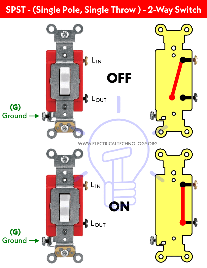
Below is a simple step by step tutorial with schematic and wiring diagram which shows how to wire single way switches in series ?
Requirements:
- Single Way Switches (SPST = Single Pole Single Through) x 2 No
- Lamp (Light Bulb) x 1 No
- Short pieces of cables x 4 No
Procedure:
Connect the two single way switches, light bulb in series to the power supply as shown in fig below. Keep in mind that both switches S1 and S2 must be closed to complete the circuit.
If there are more switches connected in series with electrical appliances i.e. light point, all of them must be at ON position to operate the load. If one of the single switches is open, the circuit won’t work then.
Click image to enlarge
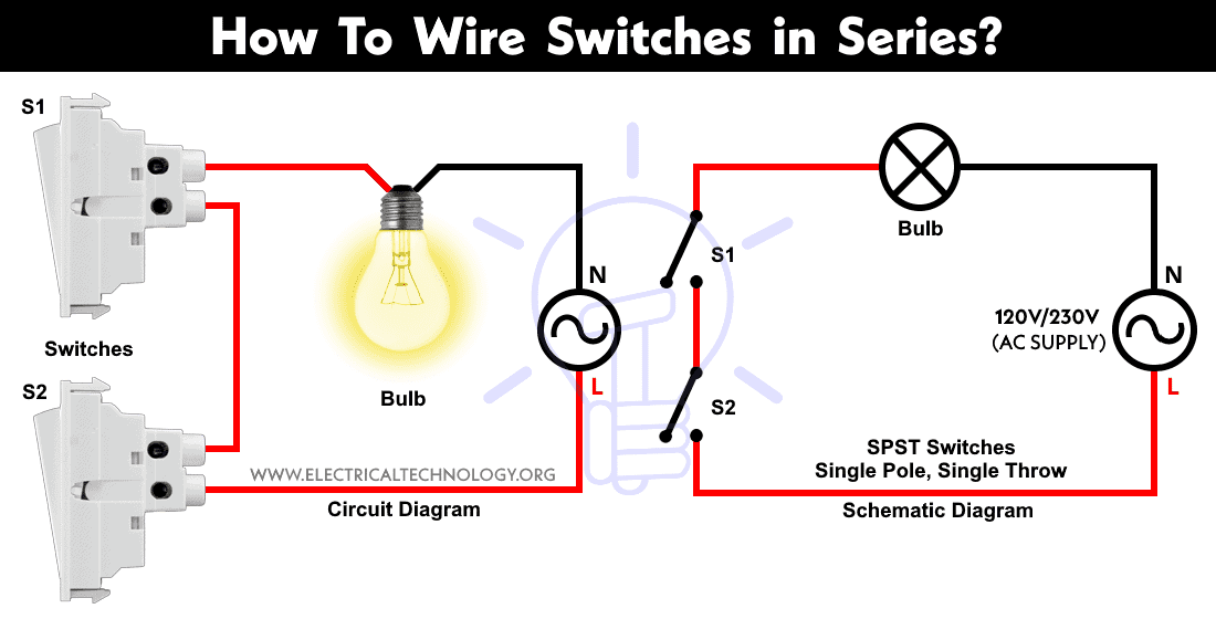
The circuit will only complete if both of the switches are at ON position. In other words, If one of the switches are open or at OFF position, the light bulb will not glow. This is the same case for other loads as well which are connected in series to control by two single way switches.
Related Wiring Diagrams:
- How to Wire 4-Way Switch (NEC) & Intermediate Switch as 3-Way (IEC)?
- How to Wire Single Pole, Single Throw (SPST) as 2-Way & 1-Way Switch? IEC & NEC
- How to Wire Single Pole, Double Throw (SPDT) as 3-Way & 2-Way Switch? IEC & NEC
Below are the different positions of single way switches and light point when connected in series.
Click image to enlarge
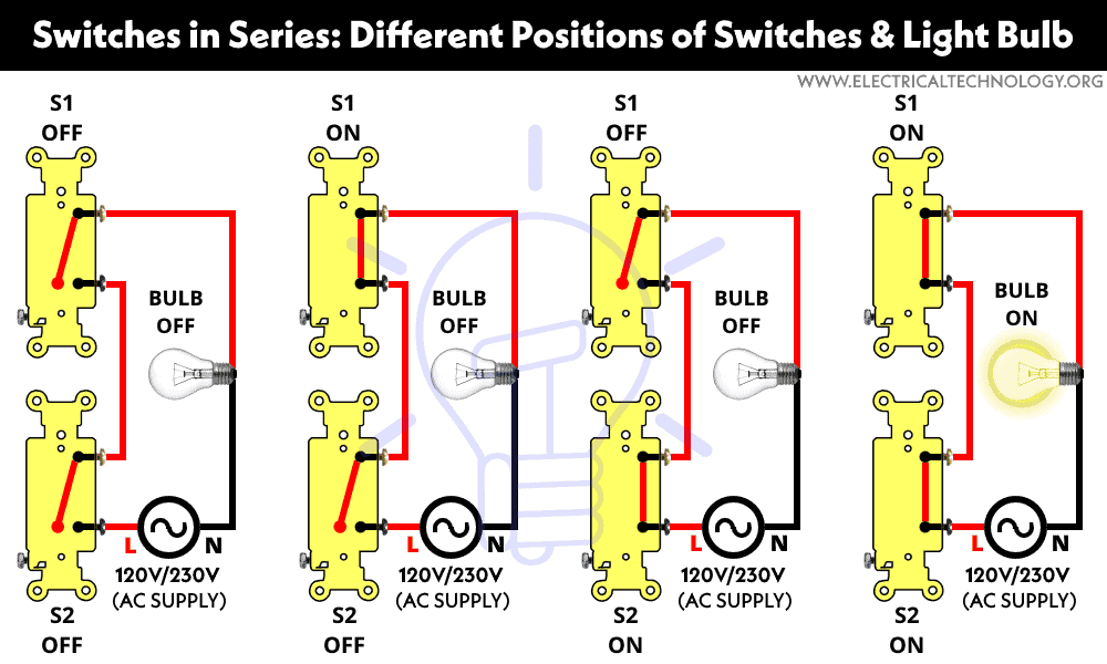
To get the switching position in ON condition for the light bulb, the above operation is the same as the Digital Logic AND Gate truth table which is given below.
| Switch 1 | Switch 2 | Lamp Position |
| 0 = OFF | 0 = OFF | 0 = OFF |
| 0 = OFF | 1 = ON | 0 = OFF |
| 1 = ON | 0 = OFF | 0 = OFF |
| 1 = ON | 1 = ON | 1 = ON |
In simple words, there are four switching positions and if both the switches are at ON position, the light bulb will glow. On the other hand, if one of the switches is at OFF position, the current will not flow in the circuit as the circuit behaves like an open circuit, hence the bulb will not glow. No matter what, all of the other connected switches are at OFF or ON positions.
The following gif shows the all positions of switches connected in series to a light bulb. It clearly shows that the light bulb is ON when both the switches are at ON position. If any one of the switches is at OFF position, The light bulb will not glow.

Here is the short video version:
Related Posts:
Good to know:
- Switches and fuses must be connected through line (Live) wire.
- Switching connections in series is not a preferred way to wire home appliances, a parallel or series-parallel wiring method is more reliable instead.
- Less wires and cables are required in this kind of wiring connection.
- It is not a reliable and comfortable method of wiring.
- Use this wiring connection when only and only it is needed to be done.
Related Electrical Wiring Installations tutorials:
- How to Wire an Outlet Receptacle? Socket Outlet Wiring Diagrams
- How to Find the Number of Outlets on a Single Circuit Breaker?
- How to Find Voltage & Ampere Rating of Switch, Plug, Outlet & Receptacle
- How to Wire a Pilot Light Switch? Wiring of 2 & 3 Way Neon Light Switches
- How to Wire Combo Switch and Outlet? – Switch/Outlet Combo Wiring Diagrams
- How to Wire an AFCI Combo Switch – AFCI Switch Wiring Diagrams
- How to Wire GFCI Combo Switch and Outlet – GFCI Switch/Outlet Wiring Diagrams
- How to Control Water Heater using Switches?
- How to Wire a Ceiling Fan? Dimmer Switch and Remote Control Wiring
- How to Wire Auto & Manual Changeover & Transfer Switch – (1 & 3 Phase)
- Automatic Bathroom Light Switch Circuit Diagram and Operation
- Staircase Wiring Circuit Diagram – How to Control a Lamp from 2 Places by 2-Way Switches?
- 2 Way Switch – How to Control One Lamp From Two or Three Places?
- How to Control a Lamp by a Single Way or One-Way Switch?
- How to control each lamp by separately switch in parallel lighting circuit?
- How to Control One Light Bulb from Five or Six Different Places using Intermediate Switches?
- Corridor Wiring Circuit Diagram – Hallway Wiring using 2-Way Switches
- Hospital Wiring Circuit for Light Control using Switches
- Hostel Wiring Circuit Diagram and Working
- Godown Wiring Diagram -Tunnel Wiring Circuit and Working
- Tunnel Wiring Circuit Diagram for Light Control using Switches
- How to Wire a UK 3-Pin Plug? Wiring a BS1363 Plug
- How to Wire a UK 3-Pin Socket Outlet? Wiring a BS1363 Socket
- How to Wire a Twin 3-Pin Socket Outlet? Wiring 2-Gang Socket
- How to Wire Combo Switch and Outlet? – Switch/Outlet Combo Wiring Diagrams
- Switch and Push Button Symbols
- Basic Electrical Wiring Diagrams


i want to ask one question why we used heer two spst siwthes it can be made with one single spst
two switches can be used in off and on particularly installed at stair.
Hello ET here Why u using 2 switches SPST switch and 2 switches in (figure 1)
Its a two way switch ..<br /><br />Means that one light is being control from two swtiches <br /><br />( Stair case , from below turn it On from switch one , and when go up , turn it off from switch 2 )
This would be a crappy way of doing it. Once you turn it off at one switch, the only way to turn it back on is from that same switch. You might as well just have one switch to eliminate having to remember which switch turned it off
ya I agree with chad.It's good for nothing to connect two switches in series
How it will work, mean to say that in first both the switches will of then when we on switch one from below stairs then how we can off the lamp by switch 2 which is already in off position?
way we use two switches in series sircuit….????
1 lamp 10 switch control &
the point of two spst switches in series is that first one acts as a “master switch” so you can cut the power without turning off the breaker. You are then free to use the second switch for normal operation.
SUB METER CONNECT HAI USKO MANE SOCKET SE DISCONNECT KARNA HAI
I need a circuit diagram of a PFC using a dual boost converter
Please define about SPST(single pole single through)
eletrical map see
Very useful website
In series the lamp shall be made ON only if all the switches are ON position… In such case a all the floor switches has to be made ON. Then only the lamp can be made ON.
its just an reference how to connect 2 SP switches in a series and both should ON to glow the Lamp., First Switch we can consider as first is the protection for second. If we use some protection unit like Fuse/MCB/RCCB etc instead of first switch den we can protect the circuit better.
Difference B/w SP & DP?
Ans: single-pole switch controls just one circuit. A double-pole switch controls two separate circuits. A double-pole switch is like two separate single-pole switches that are mechanically operated by the same lever, knob, button, or Switch.
I wired a similar circuit, 120VAC with 2 switches in series, at school and I’m a little confused about something.. when both switches were open and I put my voltmeter across the 1st switch, I got a reading of 16V. Why? What is causeing me to get this reading?
The Logic Table has a typo. Switch 1: 0 = 0FF and Switch 2: 1 = ON with Lamp: 0 = ON. It should be Lamp: 0 = OFF!
You got it. Thanks for correction.