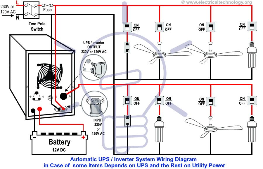
Automatic UPS Wiring for Partial Load – Remaining Load Supplied by Main Power
Suppose you have two light bulbs, one ceiling fan, and a 2 or 3-pin socket in the first room, and one light bulb, two ceiling fans, and a 3-pin 2-gang socket outlet in another room. In a second scenario, you may have all the above-mentioned electrical appliances either in a single room or distributed across different rooms, as shown in Figure 1.
Now, the electrical wiring needs to be arranged in such a way that two light bulbs, one ceiling fan, and a 2-pin socket are powered by the UPS/Inverter (using backup power stored in the batteries) without interruption during a power failure.
The remaining load will continue to rely on the main utility supply or an alternate source such as a generator or wind power. This arrangement is especially useful in cases where uninterrupted power is required for critical equipment such as a personal computer or project work.
In the following UPS/Inverter wiring diagram, it is clearly shown that when the utility power is unavailable, the connected ceiling fan, two light bulbs, and a 2-pin socket operate through the batteries and UPS. This is because the UPS output Live (Phase) wire is connected only to these appliances, while the rest remain off during a power outage.
When the main utility power is restored, all appliances and devices in the wiring system (such as refrigerator, TV, computer, fans, lights, washing machine, etc.) resume normal operation as they are supplied directly by the main source. At the same time, the inverter also recharges the batteries from the utility supply.
Keep in mind that in this wiring method, only the Live (Phase) output from the UPS is connected to the selected appliances that require continuous power, since the Neutral wire is already common and connected to all sockets and appliances in the system.
However, you may also connect both Line (Live) and Neutral from the UPS to the backup appliances if required, as discussed in our earlier UPS/Inverter wiring diagrams.
- Related Wiring Tutorial: How to Connect Automatic UPS / Inverter to the Home Supply System?
Click image or open in a new tab to enlarge
- Related Posts: Automatic UPS / Inverter Wiring Diagram using One Live Wire
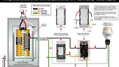
Wiring Color Code:
We have used Red for Live or Phase , Black for Neutral and Green for Earth Wire in single phase. You may use the specific area codes i.e. IEC – International Electrotechnical Commission (UK, EU etc) or NEC (National Electrical Code [US & Canada] where;
NEC:
Single Phase 120V AC:
Black = Phase or Line, White = Neutral and Green/Yellow = EGC Grounding conductor
IEC:
Single Phase 230V AC:
Brown = Phase or Line, Blue = Neutral and Green = Earth Conductor.
Good to Know: For safety, use a proper wire size of 6 AWG (16mm2 or 7/064″) conductors when connecting the suitable sized inverter / UPS to the main 120V/240V panel board or 230V consumer unit.
- Related Wiring Tutorial: UPS / Inverter Wiring Diagram With Auto & Manual Changeover Switch System.
General Precautions
- Always disconnect the power source before servicing, repairing, or installing electrical equipment.
- Use a suitably sized breaker and branch circuit conductors (properly sized wires and cables), along with switches and outlets ratings that match the required load capacity.
- Never attempt electrical work without proper guidance and safety precautions.
- Work only in the presence of experienced individuals who have practical knowledge of handling electricity safely.
- Carefully read and follow all instructions, manuals, and safety cautions before performing any electrical task.
- Remember that in some regions, doing your own electrical work is dangerous and illegal. Always consult a licensed electrician or your power supply company before making any changes to wiring connections.
- The author will not be liable for any losses, injuries, or damages resulting from the use or misuse of this information. Electricity is extremely dangerous – handle it with utmost care.
You can find more step-by-step tutorials about UPS/Inverter wiring diagrams and connections, along with detailed descriptions and operating instructions. If you are still experiencing difficulties, feel free to leave a comment in the box below.
Resources and Related Electrical Wiring Installation Tutorials.
- How to Connect a Portable Generator to the Home Supply – 4 Methods
- How Many Panels, Batteries, Charge Controller and Inverter Do I Need?
- How to Wire Solar Panels in Series, Parallel and Series-Parallel?
- How to Wire Batteries in Series, Parallel and Series-Parallel?
- How to Wire Wire a Single-Phase Distribution Board [Consumer Unit]?
- How to Wire a Distribution Board with RCD – Single Phase ?
- How to Wire 120V & 240V Main Panel? Breaker Box Installation
- Single Phase & Three Phase Wiring Diagrams (1-Phase & 3-Phase Wiring)
- Home Electrical Wiring Installation Diagrams & Tutorials
- Single Phase Electrical Wiring Installation in Home – NEC & IEC
- Three Phase Electrical Wiring Installation in Home – NEC & IEC
- How To Wire a Single Phase Energy meter?
- How To Wire a 3 Phase kWh meter?
- How to Control One Lamp From Three Different Places?
- Staircase Wiring Diagram – How to Control a Lamp from Two Places?
- Difference Between Inverter & UPS (Uninterruptible Power Supply)
- Difference Between Voltage Stabilizer and Voltage Regulator (AVR)
- How to Determine the Suitable Size of Inverter for Home Appliances?
- How to Wire Solar Panel to 120-230V AC Load and Inverter?
-
 How to Wire Smart Scene Controller Switch
-
 How to Install a Home and Away Wireless Smart Switch
-
 How to Install a Wire-Free Smart Dimmer Anywhere Companion
-
 How to Wire a Smart Wireless Switch and Anywhere Companion
-
 Wiring a Smart Dimmer Switch Companion with a Digital Dimmer
-
 How to Wire a Digital and Wi-Fi Smart LED Dimmer Switch