How to Wire a UK 3-Pin Socket Outlet? Wiring a BS1363 Socket
Wiring a 1-Gang, BS1363, 3-Pin Switched Socket Outlet Safely and Correctly
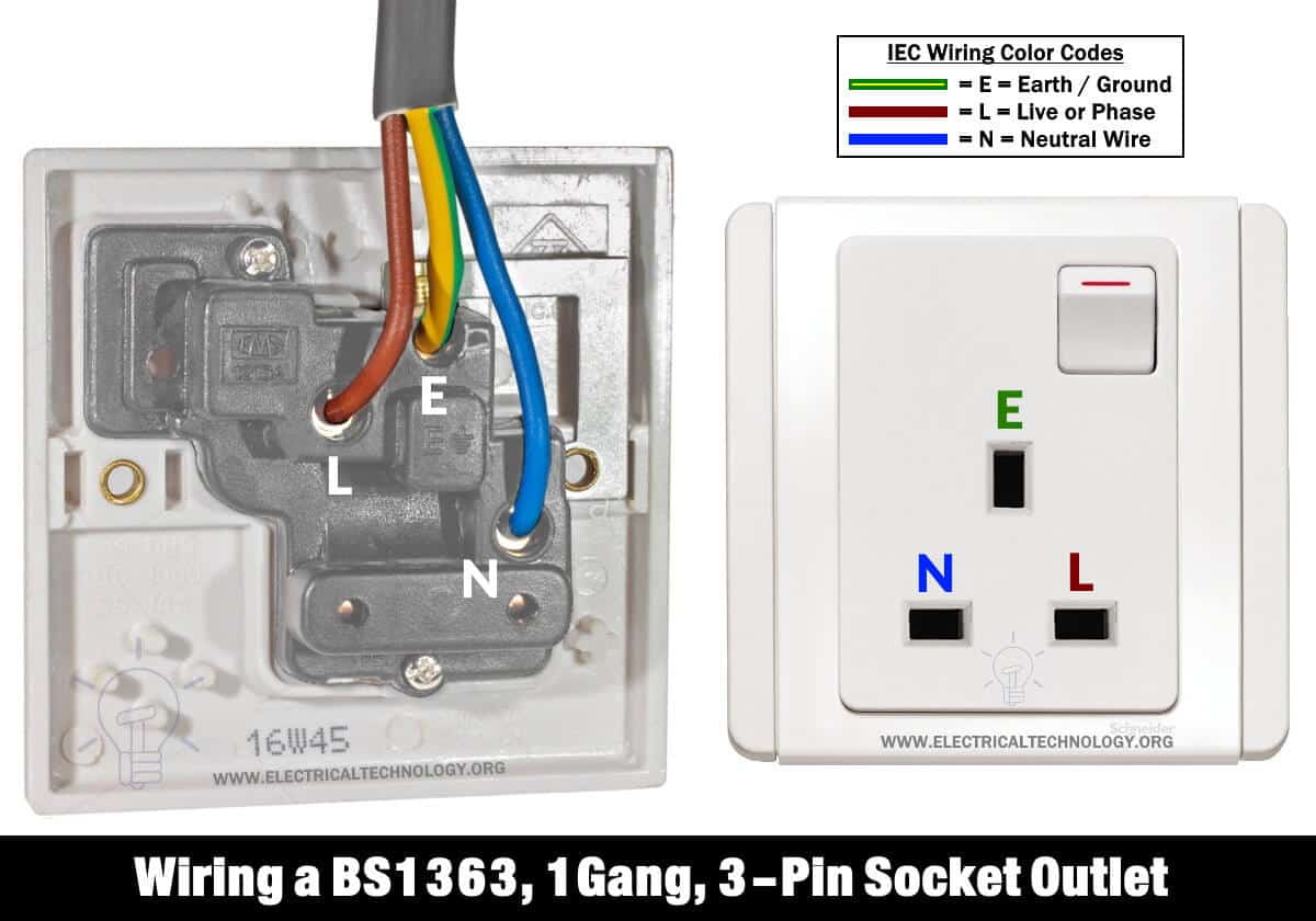
3-Pin Socket Outlet
A 3-pin socket outlet, also known as a UK socket outlet, Type G outlet, or BS1363 socket outlet according to IEC standards, consists of three pins: Live “L,” Neutral “N,” and Earth “E.” It is available in multiple varieties, including 1-gang, 2-gang, switched, and switched with a neon bulb. Wiring diagrams for each type will be provided in upcoming posts based on system needs.
The basic BS-1363 3-pin socket (wall outlet) is commonly used in the UK, IEC, and other countries following the old UK codes or IEC standards, such as UAE, KSA, Malaysia, Singapore, Cyprus, Hong Kong, India, Pakistan, Bangladesh, Malta, and so on. This is because it offers comprehensive protective features.
Click image to enlarge
Related Posts:
- How to Wire a UK 3-Pin Plug? Wiring a BS1363 Plug
- Why Earth Pin is Thicker and Longer in a 3-Pin Plug?
- How to Wire a Twin 3-Pin Socket Outlet? Wiring 2-Gang Socket
Safety Features of BS1363 Socket
The 3-Pin BS-1363 socket outlet has the following protective features.
- The Shuttered outlets (for terminals) on the socket prevents the children to insert nails or other conducting materials.
- The BS1363 power socket can’t be used as up-side down. In other words, Earth Pin can’t be inserted in the live or neutral terminal slots as the earth pin is bigger in longer in the designated 3-pin power plug. In short, it can’t be used in the wrong position even by mistake.
- The BS-1363 3-pin plug used with a 3-pin socket has a built-in fuse inside it.
- The earth slot is beggar and longer in three pin plugs, so the earth is the first pin which makes electrical contact with the circuit. In addition, the 3-pin socket can’t be used as up-side down to prevent the wrong terminal contact with other terminals (i.e. Neutral or Live as Earth).
- All the three pins in BS1363 power plug are insulated which is designed to be used with BS1363 socket.
In the following tutorial, we will show how to wire and install a new three pin socket outlet or upgrade an outdated socket (already installed).
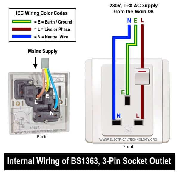
In this Switched 1, gang, 3-Pin socket, the switch is used to control the ON/OFF operation of the socket outlet as well as connected appliances. The built-in neon bulb (in the switch) indicates the ON/OFF position of the switch, plug and socket. For example, if the neon light is glowing, it means the switch is ON and the circuit is operating. If the light is not glowing, it indicates the switch is OFF and the plug, socket and appliance is disconnected from the main supply.
Click image to enlarge
Related Posts:
- How to Wire 1-Phase Split Load Consumer Unit? – RCD+RCBO
- How to Wire 230V Dual Split Load Consumer Unit? – RCD+MCB
Tools Required
The following basic tools are needed while wiring a 3-pin socket outlet.
- Switched 1 gang, 3-pin socket outlet
- Flat bladed screwdriver
- Phase tester
- Cable & Wires
- Wire snips, pliers, side cutters, scissors, knife or simple wire striper.
Wiring a BS1363, 3-Pin Socket
Follow the following simple steps to wire a BS-1363 switched socket wall outlet.
- First of all, turn off the main breaker or related MCB in the main distribution board or consumer unit and make sure the main supply is switched off.
- If you want to upgrade an already installed 1, gang, 3-pin socket, then loosen the tightly fitted screw on the front side of the wall socket. It will help to release the front cover from the mounting box. This way, the socket can be eased from the mounting box. Note: Ignore step 2 if you want to install a fully new 1-gang, three-pin power socket (wall outlet) instead of replacing or upgrading 1-gang, 3-pin socket.
- If you want to connect a new 3-pin socket, just connect the “Earth” as Green with Yellow stripe color wire into the “E” screw terminal (which indicates Earthing & Grounding).
- Now connect the “Neutral” as Blue color wire into the “N” screw terminal slot (which indicates Neutral).
- Finally, connect the “Live” as Brown color wire into the “L” screw terminal (which indicates live or phase).
- If you want to modify/upgrade the older socket outlet, just loosen the Live “L”, Neutral “N” and Earth “E” screw terminals in the previous socket and replaces the related wires in the new 3-pin power socket (Brown for Live “L”, Blue for Neutral “N” and Green or Green with Yellow stripe for Earth “E”).
- As a final step, tighten the screws and replace the front/back cover of the three-pin socket. Make sure all the wires and screws are perfectly tightened as loose connection may lead to catching a hazardous fire due to arcing and overheating or even electric shock with serious injuries. In addition, no wires or naked strands should be hanging out from the socket or screw terminals. Now, carefully push back the 3-pin socket outlet into the mounting box to place it over perfectly in the box slot.
- You have done. Restore the power back by turning ON the main switch or related circuit breaker in the consumer unit and test if it is working perfectly.
Click image to enlarge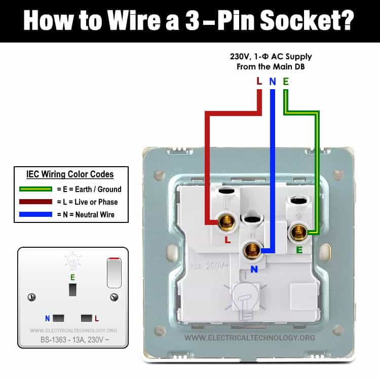
Related Posts:
- How to Wire a Three Phase, 400V Distribution Board? IEC & UK
- How to Wire Combo of 3 & 1-Φ, 400V/230V Distribution Board?
IEC & UK Wiring Color Codes:
IEC Wiring Color Codes for 230V, 1-Phase, 3-Wire System The Old UK wiring color codes for single phase wiring are as follow. 230V Single Phase
Related Posts:
Instruction & Safety Precautions
- Always disconnect the power supply and ensure it is off before servicing, repairing, or installing electrical equipment. To do this, switch off the main switch in the main consumer unit or distribution board.
- Never stand on or touch wet or metal parts when repairing or installing electrical equipment.
- Read all cautions and instructions carefully and follow them strictly when following this tutorial or performing any practical work related to electrical tasks.
- Always use the correct size of cable and wire, suitable outlets and switches, and the appropriate size of circuit breakers. You can use a Wire and Cable size calculator to determine the correct gauge size.
- Never attempt to work with electricity without proper guidance and care, as it can be dangerous and even fatal. Perform installation and repair work in the presence of experienced individuals with extensive knowledge of electrical work.
- Doing your own electrical work is dangerous and may be illegal in some cases. Contact a licensed electrician or the electric power supply provider before making any changes or modifications in electrical wiring installations.
- The author is not liable for any losses, injuries, or damages resulting from the display or use of this information, or from attempting any circuit in the wrong format. Be cautious, as electricity is extremely dangerous.
Related Wiring Installation Tutorials:
- How to Wire and Install an Electrical Outlet Receptacle?
- How to Wire a Garage Consumer Unit?
- How to Wire 240V, 208V & 120V, 1 & 3-Phase, High Leg Delta Main Panel?
- How to Wire 277V & 480V, 1-Phase & 3-Phase, Commercial Main Service Panel?
- Single Phase Electrical Wiring Installation in Home – NEC & IEC
- Three Phase Electrical Wiring Installation in Home – NEC & IEC
- How to wire a GFCI Outlet?
- How to Wire an AFCI Outlet?
- How to Wire Combo Switch and Outlet?
- How to Wire GFCI Combo Switch and Outlet
- How to Wire an AFCI Combo Switch
- How to Wire a GFCI Circuit Breaker?
- How to Wire an AFCI Breaker?
- Staircase Wiring Circuit Diagram – How to Control a Lamp from 2 Places?
- Corridor Wiring Circuit Diagram – Hallway Wiring using 2-Way Switches
- Tunnel Wiring Circuit Diagram for Light Control using Switches
- Hospital Wiring Circuit for Light Control using Switches
- Hotel Wiring Circuit – Bell Indicator Circuit for Hotelling
- Hostel Wiring Circuit Diagram and Working
- Godown Wiring Diagram – Tunnel Wiring Circuit and Working
- How to Wire 120V Water Heater Thermostat – Non-Simultaneous?
- Even More Electrical Wiring Installation & Tutorials


