How to Program PIC18 Microcontroller in C? Step by Step Guide
How to Program a PIC18 Microcontroller in C. Step by Step Tutorial (Pictorial Views)
How to Program a Microcontroller?
Microcontroller programming means coding of a microcontroller for different purposes in a special software. There are lots of software in which we can write different codes for microcontroller and IC Chips. Below, we will discuss that how to program a microcontroller.
In this tutorial, we will program or write a simple code for PIC18 microcontroller in C where “C” is a widely-used computer language and it happens to be the only supported language (aside from assembly) at this time for 8-bit and 16-bit PIC microcontrollers.
- 8 bit PIC:
PIC10, PIC12, PIC16, PIC18 are series of 8bit MCU.
- 16 bit PIC:
PIC24, dsPIC30, dsPIC33 are the series of 16 bit MCU
- 32 bit PIC:
PIC32 is the series of 32 bit MCU.
How to burn a coded program to the microcontroller?
Burning a microcontroller means to transfer the coded program from the compiler (where compiler is a software where we can write, analyze, test and debug the coded program for a microcontroller.) to the microcontroller memory.
The coding or program written for microcontroller is generally in assembly/C language and the compiler generates a hex file which is understandable by the microcontroller. The hex file contains special instructions which are to be transferred to the microcontroller memory and then it works according to the given instruction and program.
When we programmed a microcontroller (we will discuss the step by step tutorial that how to program a write the special purpose coding for a microcontroller), then we need it to burn this program to the memory of the microcontroller.
For this purpose, we need a hardware which understand and read the contents and programming codes of the hex file stored on our laptop or PC via software. So we connect this hardware via USB cable or serial to the PC/Laptop and transfer the written programming code to the memory of microcontroller and then microcontroller perform the exact function for which the designer and manufacturer designed the microcontroller IC Chip.
- Related Post: Different Types of Microcontrollers
Programming PIC18 Microcontroller in C.
Microchip Technology is the 2nd largest electronics and IC fabrication industry. Microchip Technology sells microcontrollers in 6-pin packages (PIC10F2xx series) , 100-pin packages (dsPIC33EP512MU810) and even 144-pin packages (some PIC32 devices). Also, there are many previous series like PIC12, PIC16, PIC18.
Introduction of the Target Controller:
We are going to discuss here PIC18 series. A Common Microcontroller of this series is PIC18f452. This controller is a 8 bit microcontroller has 40 pins, 32kb of program memory and it can be operate up to 40 MHZ of crystal frequency so this controller is suitable for many applications.
This controller can sink and supply up to 25mA current so no need to use a transistor to driver an LED and connecting them to other hardware. There are 3 external interrupt pins and two 16 bit timers, one 8 bit timer. This controller is equipped with Capture module and comparator module. This controller has on bard analogue to digital convertor so no need to connect external ADC with this device.
This Controller can also have modules for communication with other hardware like RS232 Module, I2C Module, 1wire Module and Parallel Slave port. This Microcontroller is the aesthetically engineered device and suitable for beginner, hobbyist as well as professional for mini and complicated electronics projects.
Introduction of the Programming Environment:
The programming environment we are going to use is MikroC for PIC. This IDE is fully equipped with a range of built in libraries and easy to use interface. This integrated development environment is packed with many calculators like hex to binary and decimal conversion which helps a lot in programming.
This Software size is also very small as compared to other software so it is easy to use and install. The Syntax of this software is a little Bit different then MPLAB Software but being a designer, I will suggest all the reader to use MikroC instead of MPLB because of it really easy to read syntax and lots of built in libraries to use.
It will definitely reduce the programming time and you don’t have to build the common functions from scratch like delay, LCD read and writes, RS232 Protocol and lots of others.
Note that MikroC is not a free software while Microchip’s MPLAB X IDE and XC8 compiler are free and offers many free libraries.
Let’s start with an example.
Note: it is considered that you have downloaded and installed the MikroC Programming Software and we are going to Program it in C and you have initial knowledge of C programming as well.
Making New Project in MikroC:
Step 1:
Double click the MikroC icon on your Desktop or where you have installed that software (as shown below).
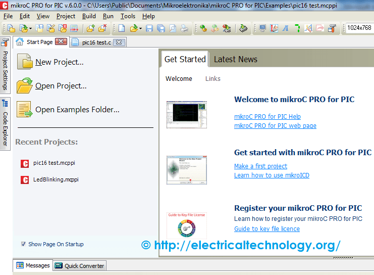
![]() After the software is loaded you will see this window.
After the software is loaded you will see this window.
Step 2:
Now go to the Project button on the upper right corner and click the “Project”.

Step 3:
Now click on “Now Project” and the new below window will appear.
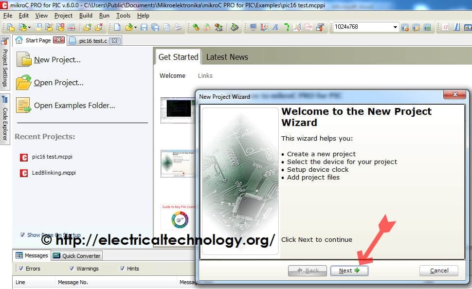
Step 4.
Now click next and select your target MCU Clock speed and project name and directory where you want to save it.
After that, don’t pay attention to the rest of the windows and just click next on all the remaining windows which appear.
Now the below window will appear. This is your programming Environment on this window you have to write code and compile it.
Now you have setup the software. Next step is writing code.
Writing Code for PIC18 Microcontroller:
PIC18f452 comes with 5 ports. Four ports are 8 bits and one port is 4 bits in this tutorial we are going to use 8 bits port. There are few things you have to keep in mind while writing code for PIC18. (Code is given below)
Making a port as input or output:
Each port has TRISX Register which defines that you are using this port for the input or for output. Where X can be, A, B, C, D, E, F e.g. TRISB.
For output you have to put 0x00 in TRISB and for input you have to put 0xFF in it. but this is not always the case because Each pin can be independently selected as an input or output. you could write 0x09 to TRISB which would select RB0 and RB3 for inputs and the rest of the pins for outputs.
Delay function:
In mikroC I have selected the delay library so I don’t have to create the delay functions here I can simply use Delay_ms() function. In this function you have to give how many mili seconds delay you want like if you want 1000 mili second delay you can write it like Delay_ms(1000).
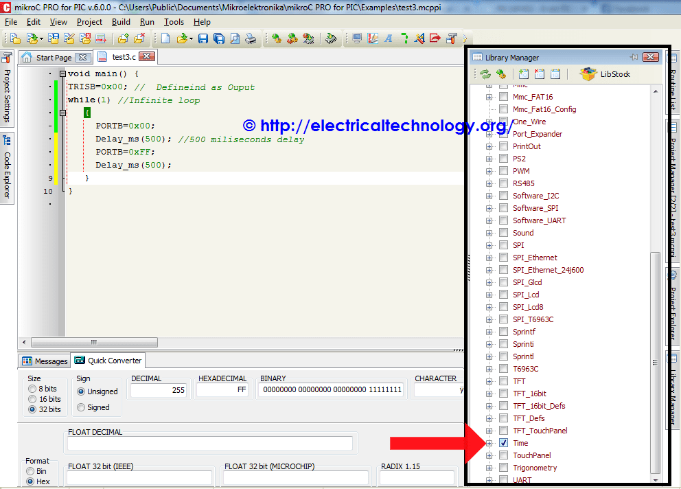
Her e is the First simple toggle PORT bits Code.
void main() {
TRISB=0x00; // Defineind as Output
While(1) //Infinite loop
{
PORTB=0x00;
Delay_ms(500) ; //500 miliseconds delay
PORTB=0xFF;
Delay_ms(500) ;
}
}
When you write this code after that you have to compile it.
Click on this “build all “button code will be compiled and hex will be created in the folder in which you have saved your project file.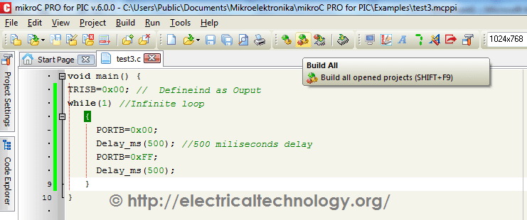
Once the hex is created you can burn this hex in your PIC18f452 by using PICKIT hardware or you can test it by using proteus.
That’s all about this first tutorial; stay tuned for upcoming posts about the topic.
Related Posts:
- Difference Between Microprocessor and Microcontroller
- Difference Between 8085 & 8086 Microprocessor – Comparison
- MAX232: Construction, Operation, Types and Application
- RS232 Serial Communication Protocol and How it Works?
- Clap Switch Circuit Electronic Project Using 555 Timer
- 10+ Design & Simulation Tools for Electrical/Electronics Engineers Online
- SMD Resistor Codes: How to Find the value of SMD Resistors


Pls i have a problem with my microcontroller(18F14K22) reading inputs. When i program my hardware (using PICKIT3) with a code like yours, it works but when i add an if condition (code below), nothing happens. What could be wrong. I also have the same results on proteus but it runs as expected on the mikroc compiler debugger.
void main() {
TRISA = 0xFF; //PORT A as inputs
TRISB = 0x00; //set PORT B pins as output
while(1){
if (PORTA.f0==1){
LATB= 0x00;
Delay_ms(1000);
PORTB = 0b11000000; //PORT B HIGH
Delay_ms(1000);
PORTB = 0b11100000;
Delay_ms(1000);
PORTB = 0b11110000;
Delay_ms(1000);
PORTB = 0b00111111; //PORT B LOW after 1sec
Delay_ms(1000);
PORTB = 0b00011111;
Delay_ms(1000);
PORTB = 0b00001111;
Delay_ms(1000);
}
}
}
can you please mail me the programme to turn on and off the led when the ultrasonic sensor get triggered in avr my mail id is praveenraturi3@yahoo.com