What is RS232 Serial Communication Protocol and How it Works?
RS232 Serial Communication Protocol: Working, Specifications & Applications
What is RS232?
RS232 is one of the standard protocol in telecommunication which is used for serial communication of data. It is basically the process of connecting signals between data terminal equipment (DTE) for example, file server, routers and application servers, such as a modem.
The standard interprets electrical features and important timings of signal and the physical size and points of the connectors. The RS232 standard has been mostly utilized in computer ports. It involves two types of communication, serial and parallel.
- Related Post: MAX232: Construction, Operation, Types and Application
What is Serial Communication?
When data is transmitted bit by bit, from a transmitter to a receiver by various networking systems, it is known as Serial Communication. It is therefore a relatively slow process than Parallel Communication.
Example to understand:
- Serial Communication – Shooting a target with machine gun.
- Parallel Communication– Shooting a target with a shotgun.
Modes of Data Transfer in Serial Communication:
- Asynchronous Data Transfer – Bits of data are not synchronized by a clock pulse. Clock pulse is a signal utilized for synchronization of operation in an electronic systems.
- Synchronous Data Transfer – The mode in which the bits of data are synchronized by a clock pulse.
Characteristics of Serial Communication:
- Baud rate is used to measure the speed of transmission. It is described as the number of bits passing in one second. For example, if the baud rate is 200 then 200 bits per Sec passed.
- Stop Bits are used for a single packet to stop the transmission which is denoted as “T”. Some typical values are 1, 1.5 & 2 bits.
- Parity Bit is the simplest form of checking the errors. There are of four kinds, i.e., even odd, marked and spaced. For example, If the number is 011, the parity bit is 0 (0 is even parity; 1 is odd parity).
Related Post: Serial Communication by Arduino
Electrical Characteristics of RS232
The electrical features refer to the specifications according to voltage levels, rate at which the signal alters and line resistance.
Voltage Levels
RS232 was known as TTL logic and therefore RS232 utilizes the TTL specific 5V and GND logic levels. In this logic “1” ranges from -15 volts to -3 volts whereas logic “0” is ranges from +3 volts to +15 volts which means logic “1” is low voltage and logic “0” is high voltage. Generally logic “0” is around +12 volts and logic “1” is around -12 volts. The voltages are paced with respect to ‘GND’, a common ground pin. Voltages that range between -3V and +3V is referred to as undetermined logic sate. Logic “1” is also referred as marking and logic “0” is referred as spacing.
Slew Rate
One of the most significant characteristics is the rate at which the signal level alters, which is called the Slew Rate. In RS232 the maximum slew rate is always kept up to 30V/ µs. Due to these limitations of standard, it helps in decreasing the cross talk with other signals.
Line Impedance
The line impedance is the resistance between the wires DTE and DCE which should be specifically from 3Ω to 7Ω. According to RS232 standard there are two different lengths of the cable. The authentic RS232 standard implies the maximum length of the cable to be 15 meters whereas the revised standards specify the maximum length related to the capacity per unit length of the cable.
Mechanical Specifications
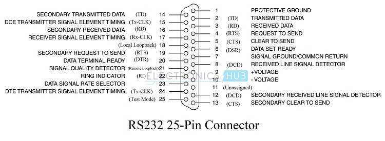
The mechanical identifications of RS232 includes the mechanical alliance of the standard. The RS232 standard strongly implies to provide a 23 – pin and D – Type connector in order to support the entire functional utility of RS232.
With the help of a DB25 Connector, the DTE object requires a female outer casing along with male whereas the DCE device uses a male outer casing with the female pins.
There are three kinds of signals in RS232, i.e data, control and ground. These function according to their direction in communication, signal types and with a variation of pins.
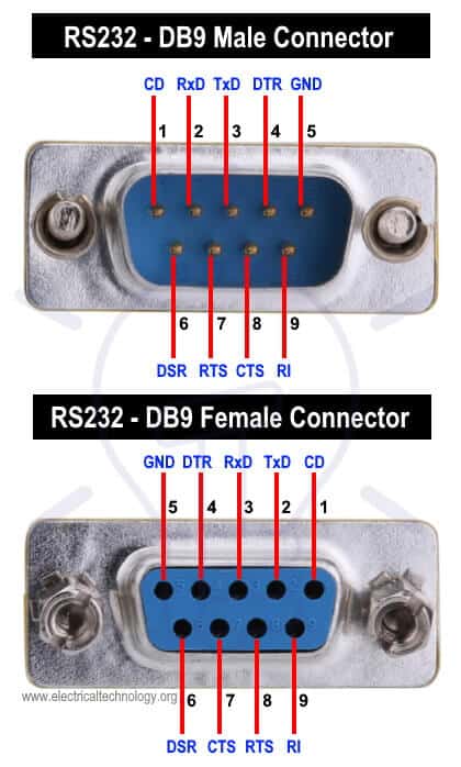
With technological advances and devices getting smaller in size, there isn’t any space for huge connector like DB25, and most of applications doesn’t require the need of connecting all the 25 pins. Therefore, a much decreased function of 9-pin connector is in use mostly. It is known as DE -9 which is a D –Type subminiature connector.
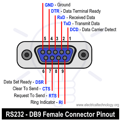
Pin Description of DB-9 Connector (RS232)
The following table shows the pins in DB9 (RS232) connector with names and DTE and DCR signal directions
| PIN No. | Signal | Name | DTE & DCE Signal Direction |
| 1 | CDC | Carrier Detect | IN from DCE |
| 2 | RxD | Receive Data | IN from DTE |
| 3 | TxD | Transmit Data | Out to DCE |
| 4 | DTR | Data Terminal Ready | OUT Handshaking Signal |
| 5 | GND | Ground | Ground Ref. Voltage |
| 6 | DSR | Data Set Ready | IN Handshaking Signal |
| 7 | RTS | Request To Send | OUT |
| 8 | CTS | Clear To Send | IN |
| 9 | RI | Ring Indicator | IN from DCE |
Functional Features
RS232 officially is known to be a complete standard that can define more than electrical and mechanical features. R232 standard has the abilities of defining functions of various signals used in the interface. The signals are known as: Common, Data, Timing and Control Signals.
Related Post: What is Fuzzy Logic System – Operation, Examples, Advantages & Applications
Procedural Specifications
The Procedural Specifications of RS232 talks specifically about the patterns of operations that are carried out when DTE and DCE wires are connected.
If a Router (DTE) is connected to a Modem (DCE) through RS232 interface. In order to send data from router to Modem, the following procedure must be used:-
- When router sends information, and the modem becomes ready to receive, it sends a DCE ready signal.
- When the router is ready to send data, it sends a Ready to send signal.
- The Modem further sends a signal called Clear to Send signal to show that data can be sent by the router.
- Lastly, the Router (DTE) sends information to Transmit Data (TD) line to the Modem (DCE).
Related Post: What is Quantization & Sampling? Types & Laws of Compression
How RS232 Works?
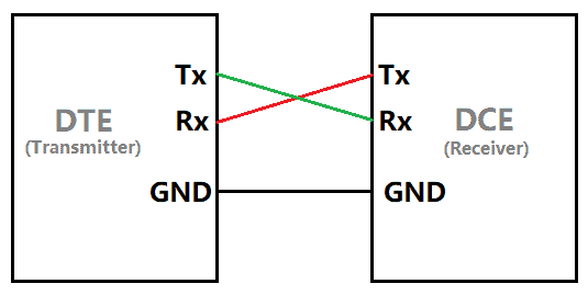
In RS232 standard devices one wire transmits a changing voltage and other wire is connected to the ground as the wires has a single end. Noise induced by differences in ground voltages of driver and receiver circuit affects the Single-ended signals. The information or data in RS232 standard is serially transmitted only in one direction over a single data line. In order to incorporate a two way communication, three wires (RX, TX and GND) are needed along with the control signals. At any moment a byte of information can be passes given the fact, the previous byte of data has been transmitted already.
RS232 strictly follows asynchronous communication protocol i.e. there is no clock signal to synchronize the sender and receiver. Hence, it needs start and stop bits to inform the receiver when to check for data. There is a delay of certain time between the transmissions of each bit. This delay is an inactive state means the signal is set to -12 volts or logic “1” as mentioned earlier that logic 1 is -12 volts and logic 0 is 12 volts in RS232.
First, the transmitter i.e. the DTE sends a Start bit to the receiver i.e. the DCE to inform it that data transmission starts from next bit. We always keep Start bit as logic 0 or +12 volts and the next 5 to 9 characters are the data bits.
If parity bit is used, the maximum bits of 8 can be transmitted and if parity bit is not used then 9 data bits can be transmitted. After successfully sending the data the transmitter sends the stop bits which can be 1 bit, 2 bits or 5 bits long.
Going by the fact that RS232 is a complete standard, many manufacturers does not follow the standards. Some of them abide by the complete identifications while some only partly follow the specifications.
This is because this variation in implementation of the RS232 standard is that not all devices and applications require the full specifications and functionality of the RS232 Protocol. For instance, a serial model which is using a RS2323 may require more control lines than a serial mouse using the serial port.
The process of transmitting and receiving which uses different identifications altogether is backed up by another process called the Handshaking.
Handshaking
Handshaking is a process that actively places the parameters of a communication between the transmitter and receiver before communication beginning. The requirement of handshaking is dependent on the speed of the transmitter at which it sends the data to the receiver and the speed at which the receiver receives it. In case of asynchronous data transmission system, there can also be no requirement of handshaking.
No Handshaking
In few transmissions where handshaking is not used, the receiver (DCE) should read the data that is already received by it before the transmitter (DTE) sends the next data. The receiver needs to use a special memory location called Buffer, as it is used at the end of the receiver it is known as Receiver Buffer.
The received data gets stored in the buffer before it is read by the receiver. The Receiver Buffer can usually store a single bit of data and this data must be read before the next data arrives and if it is not cleared, the present data will be overwritten along with the new data.

Types of Handshaking
- Hardware handshaking
- Software handshaking
Hardware Handshaking
Hardware handshaking (flow of current), lets your pc to stop from sending information and data when the device isn’t ready for it, and allows your device to prevent the computer from sending data when device is not at all ready for it.
The transmitter will transmit the data and it is loaded into the receiver buffer. This is the time, the receiver tells the transmitter not to send any further data until the data in the buffer has been read by the receiver.
The RS232 Protocol refers to four signals for the use of Handshaking:
- Ready to Send (RTS)
- Clear to Send (CTS)
- Data Terminal Ready (DTR) and
- Data Set Ready (DSR)
Related Post: Phase Locked Loop- its Operation, Characteristics & Application
Software Handshaking
Software Handshaking in RS232 needs two characters to start and end the communication. These characters are known as X-ON and X-OFF (Transmitter On and Transmitter OFF).
When the receiver sends an X-OFF signal, the transmitter stops sending the data. The transmitter will only send data after receiving the X-ON signal.

Limitations of RS232
- In order to operate RS232 needs a common platform between the transmitter and the receiver. That is why short cables are used between DTE and DCE in RS232 Protocol.
- If Baud Rate increases along with the length of the cable, there is high possibility of cross talk being held by the capacitance between the cables.
- The signal in the line is extremely receptive to noise, which can be internal as well as external.
- The voltage levels of RS232 are not adaptable with the modern system of TTL. For this, an external level converter is required.
Related Post: How to Program PIC18 Microcontroller. Step by Step Tutorial
Practical Application of RS232
The voltage levels of RS232 are very different from most of the systems designed in the recent times. Therefore, we require a level converter of some kind to implement RS232 interface. This implementation is done by dedicated level converter IC MAX232 by Maxim Integrated. These ICs takes in the RS232 signals and give out a TTL level voltages. These ICs also invert the signals as low voltage levels in RS232. For the process of serial communication Universal Asynchronous Receiver and Transmitter (UART) send and receive signals and further the signal is converted by RS232 driver between TTL and RS232 interface.
The entire system of communication mentioned in this example is of asynchronous type and it requires start, stop and parity bits which are also called as synchronization bits. The UART in the example is responsible for generating the Start, Stop and Parity bits when it transmits the data and also detects errors while receiving data.
In case of a computer and modem, the Computer and Modem communicate with each other using the RS232 interface and the communication between the modems is established using other telecommunication links.
Some additional applications of RS232 are as follow.
- Used in Servo Controllers, PLC machines, CNC Machines and other microcontroller boards.
- Other advanced protocols have easily replaced RS232 in the recent times.
- Used for serial terminals like Mouse, Modem.
Related Posts:
- Modulation – Classification and Types of Analog Modulation
- Types of Modulation Techniques used in Communication Systems
- Types of Amplitude Modulation (AM) – Advantages & Disadvantages
- Digital to Analog Converter (DAC) – Types, Working & Applications
- Analog to Digital Converter (ADC) – Types, Working & Applications
- Counter and Types of Electronic Counters
- What is GSM and How does it Work?
- What is Raspberry Pi? Creating Projects using Raspberry Pi
- What is WiMAX? Difference between Broadband WiMax and WiFi
- What is ZigBee Technology and How it works?
- What are Industrial Communication Networks?


I take that back, it’s not literally a mistake, but it’s drawn to create confusion.