Power Factor Improvement Methods with their Advantages & Disadvantages
Different Methods Used for for Power Factor Correction
The following devices and equipment are used for power factor improvement in an electrical system.
- Capacitor Banks: A bank of capacitors can be installed to reduce the reactive power demand of the load, improving the power factor. The capacitors can be fixed or switched, depending on the load requirements.
- Synchronous Condensers: A synchronous motor operating at no-load and over-excited, can be used as a synchronous condenser to improve the power factor of the system.
- Phase Advancers: Phase advancers are AC exciters connected to the rotor circuit of induction motors to improve the power factor of the motor.
- Static Var Compensators (SVCs): SVCs are solid-state devices that use a thyristor-controlled reactor (TCR) and a thyristor-switched capacitor (TSC) to provide continuous reactive power compensation.
- Active Power Filters: These filters can correct power factor issues by generating current components that cancel out harmonic distortion in the system.
- Switched Capacitor Banks: A switched capacitor bank uses automatic switching devices to vary the reactive power demand based on the load requirements, improving the power factor.
- Static Synchronous Compensator (STATCOM): A STATCOM is a voltage source converter that can provide reactive power compensation, harmonic filtering, and voltage regulation.
- Hybrid Power Filters: Hybrid power filters combine active and passive filtering techniques to provide a comprehensive solution for power factor improvement and harmonic distortion reduction.
We will discus the common methods used for power factor correction as follows:
1. Static Capacitor
We know that most industries and power system loads are inductive, which causes a decrease in the system power factor due to lagging current (see disadvantages of low power factor). To improve the power factor, static capacitors are connected in parallel with these devices operated on low power factor.
These static capacitors supply leading current, which balances out the lagging inductive component of the load current. This effectively eliminates or neutralizes the lagging component of the load current and corrects the power factor of the load circuit to enhance the overall efficiency.
To enhance system or device efficiency, these capacitors are installed near large inductive loads, like induction motors and transformers, to improve the load circuit power factor.

For example, let’s consider a single-phase inductive load shown in Figure 1, which is drawing lagging current (I), and the load power factor is Cosθ.
Figure 2 shows the load with a capacitor (C) connected in parallel. As a result, a current (IC) flows through the capacitor and leads 90° from the supply voltage. In other words, the capacitor provides leading current, and in a purely capacitive circuit, the current leads the supply voltage by 90°, which means the voltage lags 90° behind the current. The load current remains (I), and the vector sum of (I) and (IC) is (I’) which lags behind the voltage at θ2, as shown in Figure 3.
Figure 3 demonstrates that the angle of θ2 < θ1, implying that Cosθ2 is less than Cosθ1 (Cosθ2 > Cosθ1). Therefore, the capacitor improves the load power factor.
It is important to note that after power factor improvement, the circuit current is lower than the low power factor circuit current. Additionally, the active component of current remains the same before and after power factor improvement because the capacitor eliminates only the reactive component of current. Finally, the Active power (in Watts) remains the same before and after power factor correction.
Advantages:
A capacitor bank offers several advantages over other methods of power factor improvement, including:
- Low losses in static capacitors
- No moving parts, therefore requiring low maintenance
- Ability to work in normal conditions (i.e., ordinary atmospheric conditions)
- No requirement for a foundation for installation
- Lightweight, making them easy to install
Disadvantages:
However, there are some drawbacks to using a capacitor bank, which include:
- A shorter lifespan for static capacitor banks (around 8-10 years)
- The need to turn the capacitor bank ON or OFF when there is a change in load, which can cause switching surges in the system.
- Risk of damage if the rated voltage increases beyond its limit
- Expensive repair costs if the capacitors become damaged.
2. Synchronous Condenser
When a synchronous motor operates at no-load and is over-excited, it is called a synchronous condenser. When a synchronous motor is over-excited, it provides leading current and works like a capacitor.
In a synchronous motor, a separate DC source is used to excite the field winding. Therefore, the input supply only provides current to energize the stator, i.e., the current provided is in-phase with the supply voltage. So the power factor remains unity.
The power factor can be adjusted by varying the DC excitation. By increasing the DC excitation, the power factor varies from lagging to unity and leading power factor. When the DC excitation increases, the field windings are over-magnetized. The input supply provides a current component to the stator to compensate for this over-magnetization. This current leads to the supply voltage, causing a leading power factor or generating reactive power.
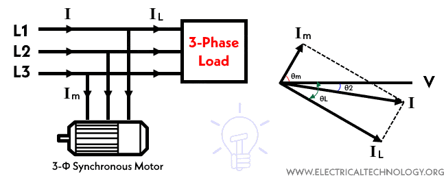
An inductive load consumes reactive power, causing a lagging power factor, while a capacitive load generates reactive power, causing a leading power factor. A synchronous motor can be used to improve the overall power factor of an electrical system by adjusting the DC excitation. The synchronous motor used specifically for power factor improvement without any mechanical load is called a synchronous condenser.
The synchronous condenser is used in parallel with the load to improve the power factor. Improving the power factor reduces the extra current drawn from the source that is wasted in the power lines. Consequently, it helps in the reduction of electricity bills and saves energy.
When a synchronous condenser is connected across the supply voltage (in parallel), it draws leading current and partially eliminates the reactive component. This way, the power factor is improved. Generally, synchronous condensers are used to improve the power factor in large industries.
Advantages:
- Long lifespan (up to 25 years)
- High reliability
- Allows for stepless adjustment of power factor
- Does not generate harmonics or require maintenance for them
- Faults can be easily removed
- Is not affected by harmonics
- Requires low maintenance (only periodic bearing greasing is necessary)
Disadvantages:
- High cost (including high maintenance costs), therefore it is mostly used by large power users
- An auxiliary device is needed for operation as synchronous motors have no self-starting torque
- Produces noise.
3. Phase Advancer
The Phase Advancer is a simple AC exciter that connects to the main shaft of a motor and operates with the motor’s rotor circuit to improve power factor. It is commonly used in industries to improve the power factor of induction motors.
Since the stator windings of an induction motor take lagging current 90° out of phase with voltage, the power factor of the motor is low. By supplying exciting ampere-turns from an external AC source, the current does not affect the stator windings, and the power factor of the induction motor improves. This process is done by the Phase Advancer.
Advantages:
- Sufficiently reduces the lagging kVAR (reactive component of power or reactive power) drawn by the motor because the exciting ampere turns are supplied at slip frequency (fs).
- The Phase Advancer can be easily used where the use of synchronous motors is unacceptable.
Disadvantage:
- Using a Phase Advancer is not economical for motors below 200 H.P. (about 150kW).
4. Capacitor Banks
The capacitor bank (published as separate & descriptive article) is connected in parallel to the load, and when the inductive load draws current from the system, the capacitor bank supplies capacitive reactive power to offset the inductive reactive power. The amount of capacitive reactive power needed to improve the power factor depends on the characteristics of the load, such as the magnitude of the inductance and the phase angle between the voltage and current.
5. Static VAR Compensator (SVC)
We have covered this topic in a separate article describing Static VAR Compensator (SVC) including a circuit diagram, construction , working principles, and applications. You can read the article to learn how SVCs are used for power factor improvement.

The following figure shows power factor improvement in a three-phase system by connecting a capacitor bank in:

Related Posts:
- Power Factor
- Causes of low Power Factor
- Disadvantages of Low Power Factor
- Advantages of Power factor improvement and Correction
- How to Calculate the Suitable Capacitor Size in µ-Farads & kVAR for P.F Improvement
- How to Convert Capacitor μ-Farads to kVAR and Vice Versa? – For P.F Correction
- μ-Farad to kVAR Calculator – How to Convert Farads to kVAR?
- kVAR to Farad Calculator – How to Convert kVAR to μ-Farads?
- Capacitor Bank in kVAR & µF Calculator for Power Factor Correction
- Capacitor Bank – Characteristics And Applications
- Power Factor Correction Calculator – How to Find P.F Capacitor in µF & kVAR?
- Active, Reactive, Apparent and Complex Power
- Difference Between Active and Reactive Power – Watts vs VA
- Introduction of Custom Power Devices For Power Quality Improvement
- Analysis of Reactive Power in Power System
- Is Reactive Power Useful? Importance of Reactive Power
- What is Static VAR Compensator (SVC)? Construction, Working and Applicators


how can we find the value of capacitor if we have to improove power factor from 0.7 to 0.8
Wait for the upcoming posts
what would be required capacity of capacitor in KVAR for improvement of power factor from 0.8 to0.9 for load of 324 KW.
which one is more efficient; capacitor bank connected in delta or star and why?
we use cappacitor bank to improve p.f in our factry and our improve running p.f is 0.99<br />
Hi, nice post got valuable information about <a href="http://www.inelecenergysaver.com/products.php" rel="nofollow">Power factor</a>. <br />Power factor improvement plays a major role in the industry, which saves lots of money and strengthens the life of the machine.
hi…. sir…….
interested in the data
Few Qu for me.
nice,thanks..need ur help…i am comparing synchronous condenser and capacitor bank,and the best in both for power factor correction on ship power distribution system..pls i need ur advice and assist,thanks
Thanks a lot it has help me so much..
1. Static Capacitor in this topic your told “lagging current which decrease the system power factor” but “when current is decreases,power factor is increases “so what is correct one