MUX – Digital Multiplexer | Types, Construction & Applications
Digital Multiplexer
What is Digital Multiplexer (MUX)?
A digital device capable of selecting one input out of its multiple input lines and forwarding it on a common output line is called a multiplexer. It is abbreviated as MUX or MPX. It is a Combinational Digital Circuit and generally called a data selector as well. In simple Words, It is the reverse of Demultiplexer (Demux).
A MUX has 2n input lines (data lines) and “n” control signal and a single output. i.e. Multiplexer has many inputs and single output.
Control signals are used for selecting a data line to be sent as output.
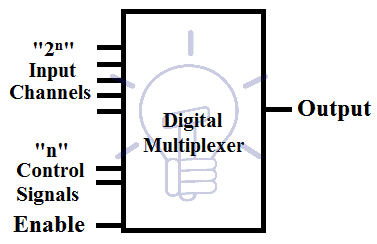
Each input line is known as a channel. A MUX can have 2n channels depending on the number of control signal “n” A MUX having Analog channel is known as analog MUX, which is used for Analog inputs.
Multiplexers are essential in communication equipment for placing many signals onto a single channel using Time Division Multiplexing (TDM) to reduce the number of the channel used per user.
Multiplexers can be used for generating any logic function. A MUX having “n” control signal can generate any logic function having “n+1” variables.
- You may also read: Ripple Carry And Carry Look Ahead Adder
Types of Multiplexer
Common types of multiplexers are as follow.
- 2 to 1 Multiplexer ( 1select line)
- 4 to 1 Multiplexer (2 select lines)
- 8 to 1 Multiplexer (3 select lines)
- 16 to 1 Multiplexer (4 select lines)
Details, circuits diagrams, schematic designs, truth tables and application of different kind of MUXES are as follow.
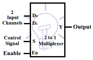
2 to 1 Multiplexer?
2 to 1 means that this multiplexer has 2 input channels and 1 output. 2 channels mean it has 1 control signal. When the control signal is “0”, the first channel is selected and the2nd channel is selected when the control signal is “1”. There is also an Enable bit used for enabling/disabling the circuit. When enable is high, MUX is enabled. When Enable pin is Low, MUX is disabled.
- You may also read: Digital Flip-Flops, SR, D, JK and T Flip Flops
2 to 1 Multiplexer Truth Table
Consider D0, D1 as input /data channel,and “S” as control signal and “Y” as output. The truth table for 2 to 1 MUX is given below.

According to the truth table, the expression for output is:
Y = S̅D0 + SD1
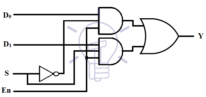
Schematic Diagram of 2 to 1 Multiplexer using Logic Gates
A MUX need AND gates equal to the number of input channels, NOT gates equal to the number of Control signals and a single OR gate.
Implantation of Multiplexer using logic gates is given below.
Implementation of Boolean Functions using 2 to 1 Multiplexer
The multiplexer is a universal logic function generator, it can implement any logic function. 2 to 1 MUX has 1 control signal so it can implement any logic function having 2 variable. Suppose I want to implement a half adder.
Half adder has 2 output functions; Sum and Carry.
For Sum; its truth table:
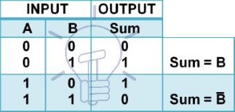
According to the table given above. When
A = 0 à Sum = B
A = 1 à Sum = B̅
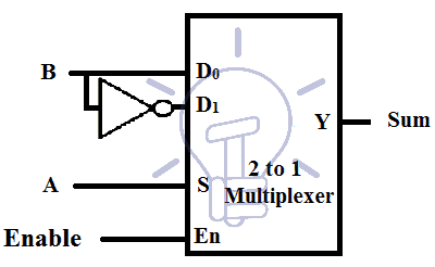
So we can use MUX where A will be used as Control Signal, when A = 0, D0 channel will be selected so we will connect D0 with B input. And when A = 1,D1 channel will get selected so we will connect B̅ with D1 as shown in the Figure given below.
Same method will be applied to“carry function”
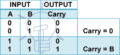
According to the table when;
A = 0 , Carry = 0
A = 1 , Carry = B
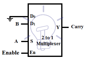
During control signal A = 0, D0 channel is selected and carry will remain 0 so we will connect channel D0 with GND (0). For control signal A = 1, D1 channel will get selected and we will connect it with B input as shown in the figure given below.
4 to 1 Multiplexer?
This multiplexer has 4 input channels, 1 output,and 2 control signals. Each binary combination of control signal will select one out of four input channels.
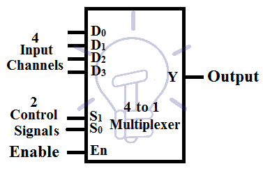
Consider D0-D3 as 4 input channels and S1S0 as control signals and Y as output.
- You may also read: Comparator and Digital Magnitude Comparator
4 to 1 Multiplexer Truth Table
The truth table for 4 to 1 Multiplexer is given below.
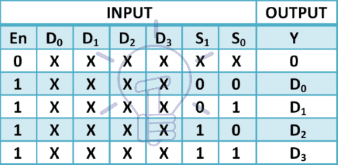
According to the truth table, the output Y is:
Y = S̅1 S̅0 D0 + S̅1S0 D1 + S1 S̅0 D2 + S1 S0 D3
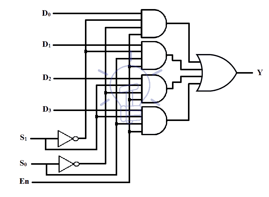
Schematic of 4 to 1 Multiplexer using Logic Gates
4 to 1 multiplexer implementation using logic gates is shown in the figure given below.
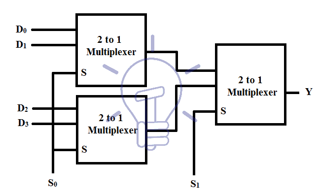
Implementation of 4 to 1 Multiplexer Using 2 to 1 Muxes
There are two configuration of making 4 to 1 MUX using 2 to 1 Muxes.
First configuration uses three 2 to 1 Muxes in a specific configuration as shown in the figure given below.
The second configuration uses 2 Muxes but it uses the enable pins of Individual Muxes as the 2nd control signal S1. Its diagram is given below.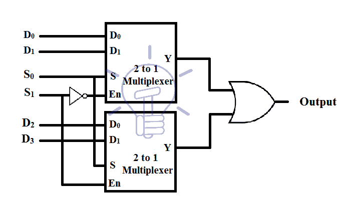
Implementing a Logic Function using 4 to 1 MUX
3 variable logic functions can be easily implemented using 4 to 1 MUX. In this example, we will implement a full adder as a full adder has 3 input variables
Full adder has 3 inputs; Cin, A and B.
Full adder has 2 output function; Sum and carry out.
For Sum; its truth table is:

According to the table , when;
{Cin, A} = {0, 0} à Sum = B
{Cin, A} = {0, 1} à Sum = B̅
{Cin, A} = {1, 0} à Sum = B̅
{Cin, A} = {1, 1} à Sum = B
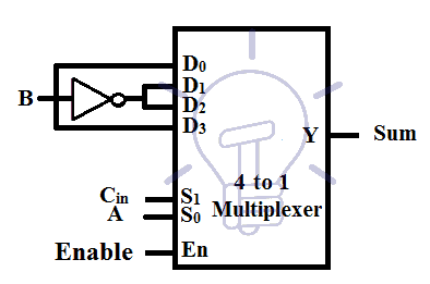
We will use Cin, A as control signal S1, S0 respectively. Channel D0, D3will be connected with B and D1, D2 will be connected with B̅.
For each combination of the control signal, its associated channel is selected and these channels are connected to the input as shown in the figure given below.
Using the same method for Carry out; the truth table is:

According to the table , when;
{Cin, A} = {0, 0} à Cout = 0
{Cin, A} = {0, 1} à Cout = B
{Cin, A} = {1, 0} à Cout = B
{Cin, A} = {1, 1} à Cout = 1
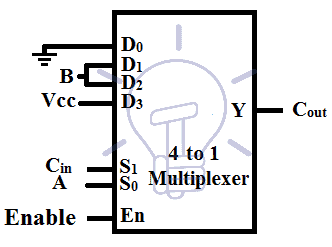
Cin, A will be used as control signal S1,S0 respectively. When control signal is {0,0}, channel D0 will be selected which is connected with GND for logic “0” . When control signal is {0,1},{1,0} channel D1,D2 will be selected respectively, which is connected with B input . The last combination of control signal is {1,1} for which channel D3 will be selected and it is connected with Vcc for logic “1”. The figure of Implementation of Cout using MUX is given below.
Also read: Counter and Types of Electronic Counters
TTL Multiplexers ICs with Pin Configuration
Some of Multiplexers IC with pin configurations is given below.
List of ICs providing Multiplexing
| S.No | IC No. | Function | Output State |
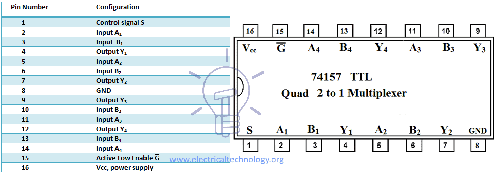
| 1 | 74157 | Quad 2 to 1 MUX | Output same as Input given |
| 2 | 74158 | Quad 2 to 1 MUX | Output in inverted Input |
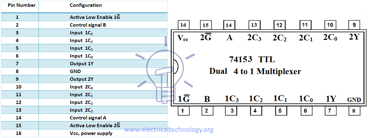
| 3 | 74153 | Dual 4 to 1 MUX | Output same as Input |
| 4 | 74352 | Dual 4 to 1 MUX | Output in inverted Input |
| 5 | 74151-A | 16 to 1 MUX | Both Outputs available (i.e. Complementary Outputs) |
| 6 | 74151 | 8 to 1 MUX | Output in inverted Input |
| 7 | 74150 | 16 to 1 MUX | Output in inverted Input |
74157 TTL QUAD 2 TO 1 Multiplexer IC & Pin Configurations
74153 TTL Dual 4 TO 1 Multiplexer IC & Pin Configurations
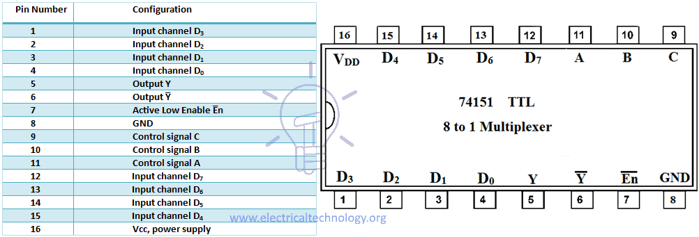
74151 TTL 8 TO 1 Multiplexer IC & Pin Configurations
Applications of Multiplexers (MUX)
Multiplexer has an important rule In digital system applications, some common applications of MUX in digital electronics as follow:
- Multiplexers are used in data routing application to rout the data in sequence and particular directions well as destination as a single output from several input signals.
- It is used as logic function generator where logical expression (Boolean algebraic functions) can be generated instead of logic gates.
- MUX can be also used to convert the parallel data in serial data. parallel to serial conversion is needed in measurement. testing, military, aerospace data communication and telecommunication.
- In Communication systems, a Multiplexer is used to increase the efficiency of the communication system (i.e. Audio & Video signals) from different channels in cables and wires in transmission systems and communication network.
- In telephone network, multiplexer can be used to isolate the multiple audio signals and the single audio signal can be reach to the desired recipients.
- In computer memory, Multiplexer (MUX) has been used to maintain large amount of data as well as reduce the number of copper lines needed to connect the computer memory to other parts of the system.
- It is also used to transmit the data signals from the computer system of a satellite or spacecraft to the ground system by using a “GSM” (Global System for Mobile Communication) and “GPS” (GPS (Global Positioning System) satellite.
- Multiplexers also used in waveform generators, pulse train generators, register to register data transfer, control sequencers, encoders etc.
You may also read:


Thank you for clear explanation.
Now I know the difference between MUX and DEMUX. Thanks for the detailed information.