DEMUX – Demultiplexer | Types, Construction & Applications
Digital Demultiplexer (Demux)
What is Digital Demultiplexer (Demux)?
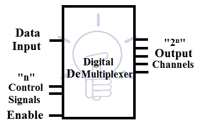
A digital device capable of forwarding its single input onto any one of the output lines is called Demultiplexer abbreviated for DEMUX. It is the reverse of Multiplexer.
A Demultiplexer has a single input and multiple outputs. It has 2n output lines where “n” is the number of control signals. Each combination of control signal selects a specific output line through which the input data signal should flow out. These output lines are known as channels. Demultiplexer’s operation is exactly opposite of Multiplexer.
Demultiplexer provides its input data a specific direction to flow through.
It can convert a serial data signal into parallel data signals thus it can be used as serial to parallel converter.
In communication, the receiver on receiving end receive a serial data signal on a single line which contains many data signals. These signals are extracted through Demux onto separate lines and reconstructed back together as the original signal.
It is also used for storing data inside memory unit. Each register is connected with single Demux. There is no need for a separate data line to each of the registers, a single Demux can store data in all connected registers.
- You may also read: Ripple Carry And Carry Look Ahead Adder
Types of Demultiplexer
Common types of multiplexers are as follow.
- 1 to 2 Demultiplexer ( 1select line)
- 1 to 4 Demultiplexer (2 select lines)
- 1 to 8 Demultiplexer (3 select lines)
- 1 to 16 Demultiplexer (4 select lines)
Details, circuits diagrams, schematic designs, truth tables and application of different kind of MUXES are as follow.
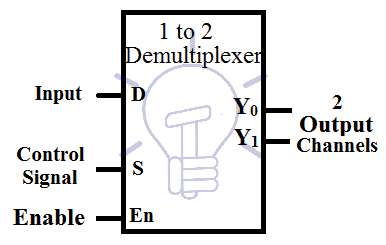
1 to 2 Demultiplexer
This Demux has 2 output channels and 1 control signal. When the control signal is “0”, the first output channel is selected. When the control signal is “1”, the second output channel is selected as a route for input data. There is also an Enable bit used for enabling or disabling the circuit. It can be active high or active low.
- You may also read: Digital Flip-Flops, SR, D, JK and T Flip Flops
Truth Table
Consider input as D and output as Y0,Y1,and Control signal S. the truth table of 1 to 2 Demultiplexer is:
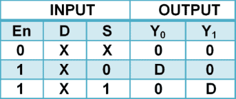
According to the truth table given above, the output expression is:
Y0 = S̅D
Y1 = SD
Schematic Diagram of 1 to 2 Demultiplexer using Logic Gates
Schematic of 1 to 2 Demultiplexer using logic gates is given below.
Demultiplexer needs And gates equal to the number of output channels and NOT gates equal to the number of Control signals.
- You may also read: Comparator and Digital Magnitude Comparator
1 to 4 Demultiplexer?
1 to 4 means that this demultiplexer can distribute I data line into 4 separate data lines. so this Demux has 4 output channels and to control 4 channel it needs 2 control signals.
Each binary combination of control signal will select a separate output channel.
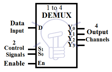
Consider D as input data, Y0-Y3 as 4 output channels and S0,S1as the control signals and there is an active high enable pin En.
Truth Table
The truth table for 1 to 4 demultiplexer is given below.

According to the Truth table given above the output expression is;
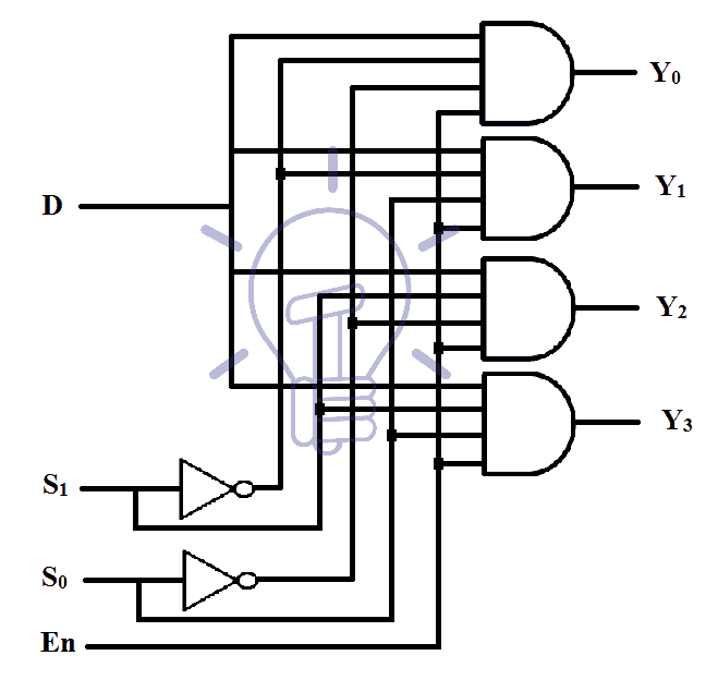
Y0 = S̅1 S̅0 D
Y1 = S̅1 S0 D
Y2 = S1 S̅0 D
Y3 = S1 S0 D
Schematic of 1 to 4 Demultiplexer using Logic Gates
Implementation schematic of 1 to 4 DeMux using logic gates is given below.
Implementation of 1 to 4 Demultiplexer Using 1 to 2 Demultiplexers
There are two configurations of making a 1 to 4 Demultiplexer using individual 1 to 2 Demultiplexers.
The first one uses 3 1-2 DeMux and the second one uses 2 1-2 DeMux.
1st configuration:
This method uses 3 individual DeMux and provides a separate Enable pin to enable/disable the whole block.
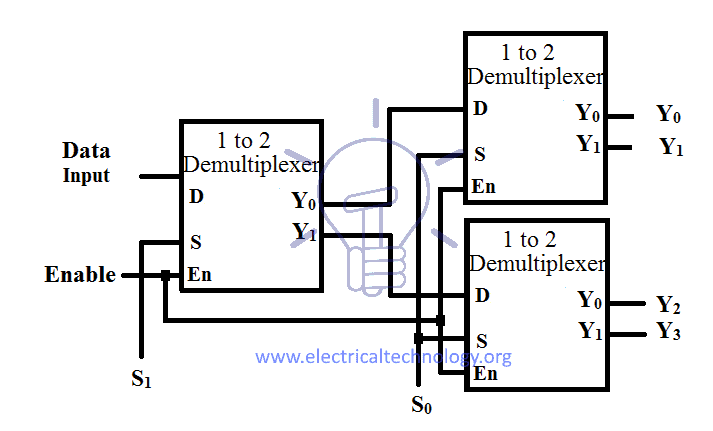
2nd configuration:
This method uses the Enable pins of individual DeMuxes as a control signal and Switch ON/OFF the specific individual DeMux when the control signal is applied.
For S1 = 0, only upper DeMux will activate and output Y0 / Y1 will get selected.
For S1 = 1, only lower DeMux will activate and output Y2 / Y3 will get selected.
1 to 8 Demultiplexer?
This DeMux can direct one data line onto 8 separate output channels and these 8 channels are controlled by 3 control signals.
Truth Table
Consider D as input data and Y0-Y7 as the 8 output channels and S0,S1,S2 as control signals. En is the active high Enable input. So the truth table for 1 to 8 DeMultiplexeris :
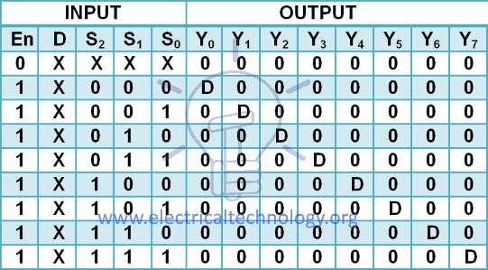
According to the 1-8 DeMux truth table, output expressions are:
Y0 = S̅2 S̅1 S̅0 D
Y1 = S̅2 S̅1 S0 D
Y2 = S̅2 S1 S̅0 D
Y3 = S̅2 S1 S0 D
Y4 = S2 S̅1 S̅0 D
Y5 = S2 S̅1 S0 D
Y6 = S2 S1 S̅0 D
Y7 = S2 S1 S0 D
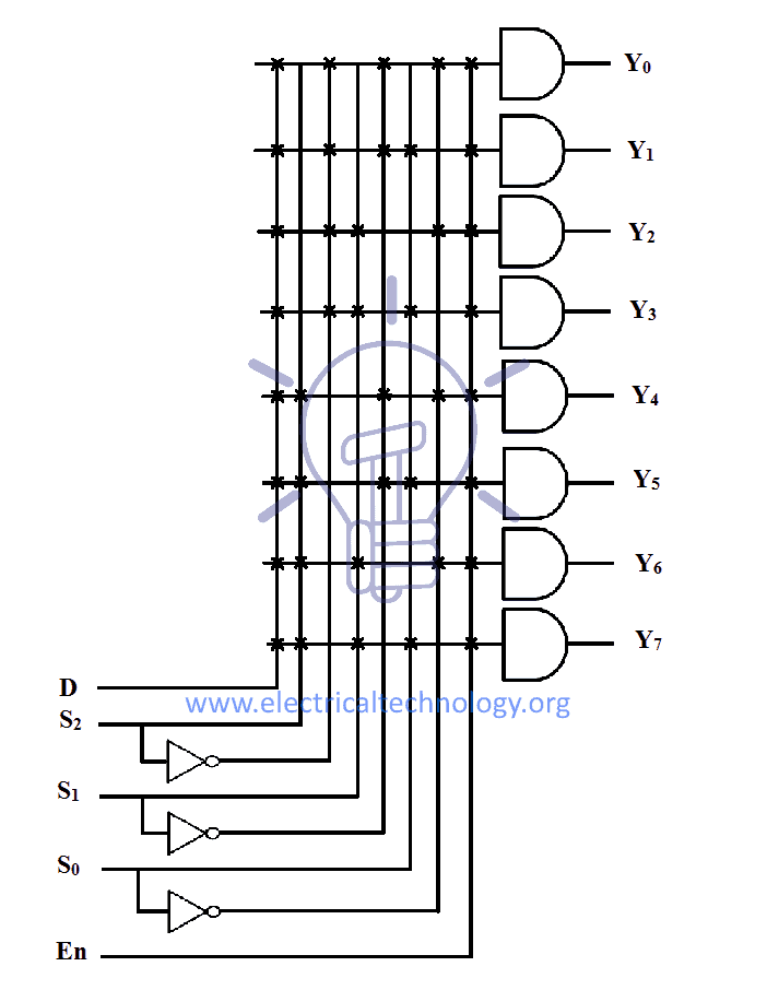
1 to 8 DeMux Schematic Diagram using Logic Gates
Schematic of 1 to 8 Demultiplexer using logic gates is given below.
1 to 8 DeMux Using 1 to 4 DeMultiplexers
There are two configurations of making 1 to 8 DeMux using individual 1 to 4 DeMuxes.
The first one uses two 1-to-4 DeMuxes and a 1-to-2 DeMux. The second one only uses two 1-to-4 DeMux.
1st configuration:
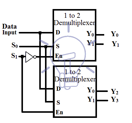
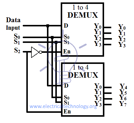
This method uses two 1-to-4 DeMuxes connected together in parallel which is connected with a 1-to-2 DeMux in cascade as shown in the figure given below. This configuration gives a separate Enable pin to enable or disable the circuit.
2nd configuration:
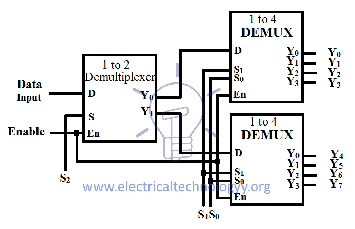
This method uses only two 1-to-4 DeMuxes connected together in parallel. The only difference is that the Enable pins of the individual DeMuxesare used as the 3rd Control signal S2.
This enable pin is used to Enable or Disable one of the two individual DeMuxes.
Demultiplexer IC with Pin Configuration
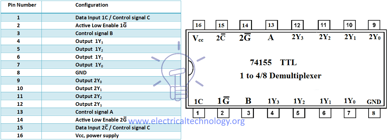
74155 IC is a Decoder/Demultiplexer IC which can be used as a 2-4 decoder or 3-8 decoder or 1-4 Demultiplexer or 1-8 Demultiplexer. Its pin configuration is shown in the table given below.
This IC gives inverted output except for Data input 2C pin(15) in case of 1 to 4 Demultiplexer. It can be used as 1 to 8 Demultiplexer if pin (1) and Pin (15) are combined together to form Control signal C. and combine Strobe pin (2) and Pin(14) to use as Data input.
74155 TTL 1 to 4/8 Demultiplexer with Pin Configurations
Applications of Demultiplexer (Demux)
The main function of Demultiplexer is to enable or select single output signal out of many inputs signals, therefore, they are widely used in microprocessor, computers and digital electronics as follow:
- Demultiplexer (Demux) and Multiplexer (MUX) both are used in communication systems to carry multiple data signals (i.e. audio, video etc) using single line for transmission. In this easier process, Demultiplexer receive the output data of Multiplexer (as a receiver) and covert back them to the original form then.
- In Arithmetic logic unit (ALU), the output of ALU can be stored in storage unit (multiple registers) by using Demultiplexer. In this process, the output of ALU is connected as input to the Demultiplexer and the output of Demultiplexer connected to the registers to store the data.
- Demultiplexer is also used in serial to parallel converter. In this process, serial data has been connected as input to the demultiplexer at a regular interval. In addition, a counter is attached as control input to the Demultiplexer to detect the data signal of Demultiplexer outputs. When all data signals are stored, the output of the Demux can be read out in parallel i.e. parallel data can be read from the incoming serial data stream.
Demultplexer (Demux) are also used in following systems.
- To enable the different rows of memory chips depends on the address.
- To chose different banks of memory.
- To enable different functions unit in the system
- To select different IO devices fro data transfer
- Demux also used for synchronous data transmission systems
- Boolean function implementation
- Data acquisition systems
- Combinational circuit design
- Automatic test equipment systems
- Security monitoring systems
You may also read: