Types of Passive Low Pass Filters – RL and RC Passive Filters
What is Low Pass Filter? Passive Low Pass Filter & Its Types With Examples.
A passive low pass filter is a type of low pass filter that is made up of passive electronic components such as resistor, capacitor & inductor. The gain of a passive low pass filter is always less than or equal to 1. So its output signal’s amplitude is always less than it’s input signal’s amplitude. However, they are simple & easy to design. In this article, we will discuss the passive low pass filter & its types with examples.
- Related Post: Filters, Types of Filters and Their Applications
Low Pass Filter
Low pass filter or LPF is a type of filter that allows low-frequency signals and blocks high-frequency signals. The frequencies lower than a selected frequency known as the cut-off frequency are passed while any frequency higher than cut-off frequency is blocked by the filter.
Low pass filters are of two types:
We will only discuss the passive low pass filter in this article as active low pass filters are already explained in another post. Passive low pass filters are classified according to the order of the filter. we will discuss 1st & 2nd order low pass filter.
- Related Post: Types of Passive High Pass Filters
First Order Low Pass Filter
First order low pass filter is the simplest form of low pass filters that are made of only one reactive component i.e Capacitor or Inductor. A resistor is used with the Capacitor or Inductors to form RC or RL passive low pass filter respectively. RC & RL low pass filters are briefly discussed below with examples.
- RC Low Pass Filter
- RL Low Pass Filter
RC Low Pass Filter
The most simple passive low pass filter is made of a resistor connected in series with a capacitor & the output is taken across the capacitor as shown in the figure below.
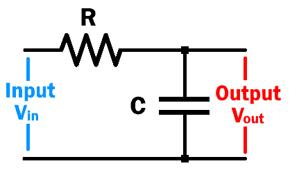
As we know that the capacitor allows a high-frequency signal (operate as short wire) & block low-frequency signal (operate as open wire). So, when a low frequency is applied to the circuit, the capacitor will become open & the signal will appear across its terminal, which will eventually flow out as output. However, when the high-frequency signal reaches the capacitor it becomes a short circuit & the output becomes zero.
The reason the capacitor blocks & allows frequency is because of its reactance which is given by.
Xc = 1/C = 1/(2πfC)
Where Xc is the reactance of the capacitor
f is the applied signal’s frequency
C is the capacitance of the capacitor
From the above equation, we can say that the capacitive reactance Xc is inversely proportional to the applied frequency f. if the applied frequency is too low, the reactance Xc will be greater than the resistance of the resistor & the input signal will be established across the capacitor. But when the frequency f goes higher, the reactance Xc becomes lower than the resistor’s resistance. This results in a low voltage drop (almost negligible) across the capacitor as compared to the resistor.
- Related Post: Types of Active High Pass Filter
Frequency Response:
The frequency response, also known as bode plot of a circuit shows the output to input ratio for a specified frequency range. The frequency response of Low Pass Filter is given below:
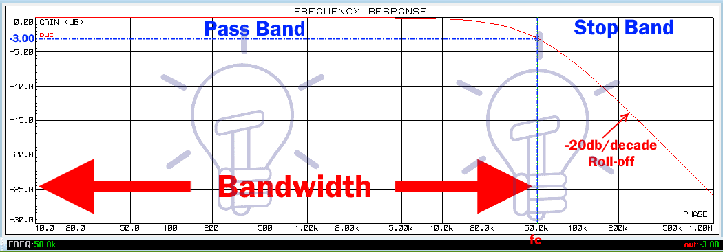
It contains some key points such as the cutoff frequency fc, passband, stopband, bandwidth & roll-off etc.
Cutoff Frequency:
Cutoff frequency, also known as corner frequency denoted by fc is the selected frequency point where the output signal’s power becomes -3db or 70.7% of the input signal. At this frequency, the capacitive reactance Xc & resistor’s resistance R become equal.
The low pass filter allows frequency below the cutoff frequency and blocks any frequency higher than the cutoff frequency.
Where the cutoff frequency is calculated by :
R = Xc
R = 1/(2πfC)
fc = 1/(2πRC)
- Related Post:Types of SSR Relays – Construction & Operation
PassBand:
The passband is the range of frequency that gets passed through the filter. In the low pass filter, the passband frequency is lower than the cutoff frequency fc.
StopBand:
The stopband is the range of frequency which is blocked by the filter. In low pass filter, the range of frequency higher than the cutoff frequency fc is referred to as stopband.
Bandwidth:
The bandwidth of the filter is a range of frequency that gets passed without any attenuation. The low pass filter allows frequency from 0 Hz to fc Hz. So its bandwidth is fc-0 = fc Hz.
Roll-off:
When the frequency increases and reaches the cutoff frequency the gain of the filter starts to decrease. The rate of decrement of the gain is known as roll off.
The roll off of a 1st order low pass filter is -20db per decade.
- Related Post: Types of Rectifiers and Their Operation
Output Voltage:
To calculate the output voltage of a passive low pass filter at any frequency, the voltage divider rule is applied between the resistor and capacitor. So, the output voltage vout is given by.
Vout = Vin * (Xc/Z)
Where
Xc =capacitive reactance
Z = total Impedance of circuit
Z = R + jXc
Z = √(R2 + Xc2)
So
Vout = Vin * (Xc/√(R2 + Xc2))
Where Xc = 1/(2πfC)
Gain:
Gain in the ratio of output voltage to input voltage.
Gain = Vout/ Vin
This gain is usually described is dB, which is the logarithmic form of the gain & it is given by:
GaindB = 20 log (Vout/Vin)
Notice the gain of the passive low pass filter in the frequency response graph given above. The maximum gain remains 0dB. In an active filter, this gain can be modified according to the requirement.
- Related Post: Types of Diodes and Their Applications
Example :
Let’s take an example of an RC low pass filter with the resistor R of 1K & capacitor C of 47 nF.
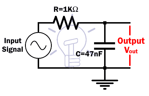
The cutoff frequency fc is calculated as:
fc = 1/(2πRC)
fc = 1/(2π*103*47*10-9 )
fc = 3.38 KHz
Frequency response simulation using Proteus for the given RC low pass filter is
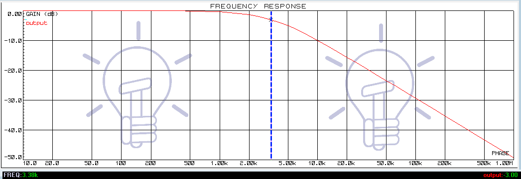
It clearly shows -3dB gain at 3.38KHz, which is the cutoff frequency of this filter.
This filter will allow any frequency below 3.38KHz and block any frequency greater than 3.38KHz. Thus its bandwidth is 3.38KHz.
RL Low Pass Filter:
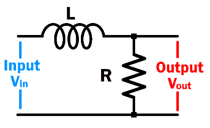
This type of low pass filter is made from a resistor & Inductor in series where the output is taken across the resistor as shown in the figure below.
The inductor allows the low-frequency signal to pass which eventually establishes across the resistor and it blocks high-frequency signal which does not make it to the load resistor.
Inductor provides low reactance for low-frequency signal & high reactance for a high-frequency signal. Its reactance is given by:
XL = L = 2πfL
According to the equation above, the inductor reactance is directly proportional to the input signal’s frequency.
So when the input signal’s frequency is low, it reactance will be lower than the resistance of the resistor. Thus, the resultant input signal’s voltage drop will be maximum at the load resistor.
When the input signal’s frequency increases, the inductive reactance XL becomes greater than the resistor’s resistance R. Due to which the result is a negligible voltage drop at the load resistor. thus the input signal gets blocked.
- Related Post: Counter and Types of Electronic Counters
Frequency Response:
The frequency response of RL low pass filter is similar to RC low pass filter.
The cutoff frequency of the RL low pass filter is given by:
At cutoff frequency, the reactance is equal to the resistance
XL = R
2πfl = R
fc = R/(2πL)
Where
L = inductance of the inductor
R = Resistor’s resistance
Output Voltage:
The output voltage at any frequency can be calculated by voltage divider rule.
Vout = Vin * R/Z
Where Z = total impedance of the circuit.
Z = R +JXL
Z = √(R2 + XL2)
So
Vout = Vin * R/√(R2 + XL2)
Where XL = 2πfL
Example:
In this example we will take 1K resistor & 3mH inductor.
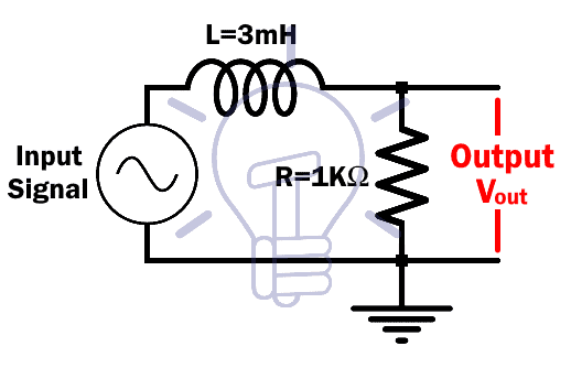
We will calculate the cutoff frequency for this circuit.
fc = R/(2πL)
fc = 103/(2π*3*10-3)
fc = 53kHz
Let’s simulate this circuit using Proteus. The frequency response using proteus is given below:
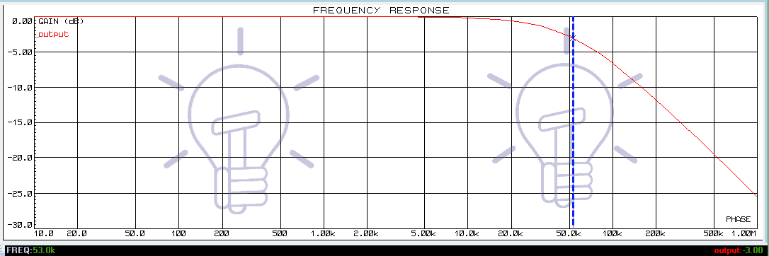
It clearly shows the -3dB (cutoff frequency) point where the frequency is 52.9 KHz which is almost equal to 53KHz.
Second Order Passive Low Pass Filter
Second order low pass filter is made by cascading two first order low pass filters. The first order low pass filter can be RC or RL circuit. We will discuss both with examples.
- Related Post: Types of Digital Latches – SR D Latches
RC Low Pass Filter
Two 1st order RC low pass filter are cascaded together to form 2nd order low pass filter. The schematic of 2nd order RC low pass filter is given below;
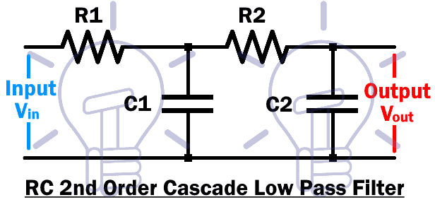
The first order Low pass filter stage is made of R1C1 & second stage is made of R2C2.
The output can be taken from either of the two stages. The first stage will provide 1st order low pass filter output with a roll off of -20db/decade. The second stage will provide 2nd order low pass filter output with a steeper roll-off of -40db/decade. Its frequency response is shown below.
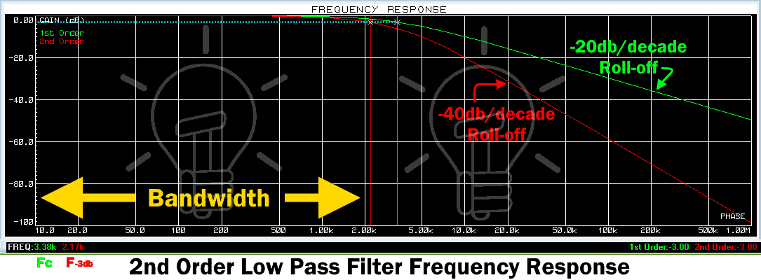
The green signal shows the frequency response of 1st order low pass filter with -20db/decade roll-off. The red signal shows the frequency response of 2nd order low pass filter with -40db/decade roll-off.
Cutoff Frequency:
The cutoff frequency or corner frequency fc of 2nd order low pass filter is given by
fc = 1/{2π√(R1R2C1C2)}
If the resistor R=R1=R2 & Capacitor C=C1=C2, then
fc = 1/(2πRC)
Gain at Corner Frequency:
The gain of general n order low pass filter at corner frequency is given by:
Gain = (1/√2)n
So the gain of 2nd order low pass filter at corner frequency fc is
Gain = (1/√2)2 = 0.5
The gain in dB will be:
Gain(dB) = 20 log (0.5) = -6dB
So the gain of 2nd order LPF at cutoff frequency is -6db.
-3dB Frequency:
The calculated corner frequency fc provides -6dB gain whereas, the filter passband frequency lies at a –3dB gain which is calculated as:
f (-3db) = fc√(2(1/n)-1)
Where n is the order of the filter & fc is the calculated corner frequency. The f(-3db) decrease with the increase in the order of the filter. This implies that the increasing order of the filter provides a steeper or fast roll off.
- Related Post: Types Of Capacitors | Fixed, Variable, Polar & Non-Polar
Example
In this example we have taken resistor R1 = 1K, R2 = 10K & capacitor C1 = 47nF , C2 = 4.7nF
The cutoff frequency of this circuit will be
fc = 1/{2π√(R1R2C1C2)}
fc = 1/{2π√(103*10*103*47*10-9*4.7*10-9)}
fc = 3.38 KHz
This frequency lies at -6dB gain. Now we will calculate f (-3db)
f (-3db) = fc √(2(1/2)-1)
f (-3db) = 3.38*103 √(2(1/2)-1)
f (-3db) = 2.17 KHz
So this low pass filter will allow frequency less than 2.17 KHz, thus its bandwidth is 2.17 KHz.
Let’s simulate this example using Proteus. The following is the frequency response of the said example.
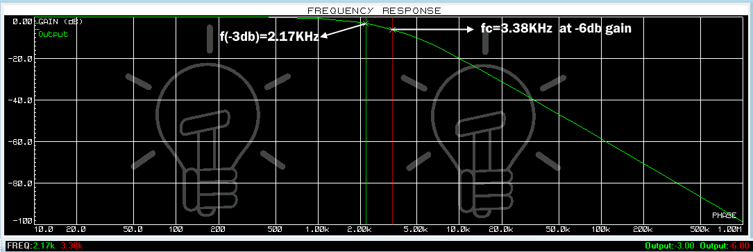
This graph clearly shows the -3dB frequency at 2.17KHz which we calculated earlier.
RL Low Pass Filter:
Two stages of RL low pass filter are cascaded together to form 2nd order low pass filter. The first stage consists of L1R1 & the second stage consist of L2R2. It schematic is given below.

The 1st stage is a 1st order low pass filter whose output provides a roll off of -20db/decade. The 2nd stage provides 2nd order low pass filter with a roll-off of -40db/decade.
Corner Frequency
The corner frequency or cutoff frequency fc of 2nd order low pass filter is given by.
fc = {√(R1R2)}/{2π√(L1L2)}
If the resistor R=R1=R2 & Inductor L = L1 = L2, then
fc = R/(2πL)
Gain at Corner Frequency:
The gain at corner frequency is given by:
Gain = (1/√2)n
Where n is the order of the filter. So the gain of 2nd order Low pass filter is:
Gain = (1/√2)2 = 0.5
The gain in dB is
Gain(dB) = 20 log (0.5) = -6dB
-3dB Frequency
The actual cutoff frequency of a filter lies at –3dB gain. To calculate -3dB frequency we will use:
f(-3dB) = fc√(2(1/n)-1)
Where n is the order of the filter.
- Related Post: Different Types of Sensors with Applications
Example:
Lets take resistor R1 = 1K, R2 = 10K & Inductor L1 =3mH, L2 = 30mH.
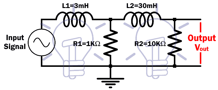
We took R2>10R1 & L2>10L1 because of the loading effect explained earlier. The impedance of the succeeding stage needs to be at least 10 times higher than the previous stage.
The cutoff frequency of this filter is
fc = {√(R1R2)}/{2π√(L1L2)}
fc = {√(103*10*103)}/{2π√(3*10-3*30*10-3)}
fc = 53 KHz
The frequency lies at -6db so we will calculate -3db frequency, which is given by:
f(-3dB) = fc√(2(1/2)-1)
f(-3dB) = 53*103√(2(1/2)-1)
f(-3dB) = 34.11 KHz
This is the -3dB frequency of this filter. The Proteus simulation of this filter is given below.
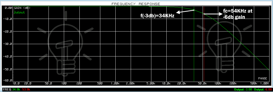
The graph shows the -3dB gain where the frequency is 34.11 KHz. and you can clearly see the difference between the roll off of 1st & 2nd order low pass filters.
Limitations of Passive Low Pass Filter:
- There is no amplification of the input signal in a passive low pass filter.
- Its gain remains less than or equal to 1.
- Cascading stages for higher order passive filters results in the loss of amplitude of the signal.
- The load impedance affects the characteristics of the filter.
Related Post: Resistor & Types of Resistors | Fixed, Variable, Linear & Non-Linear


