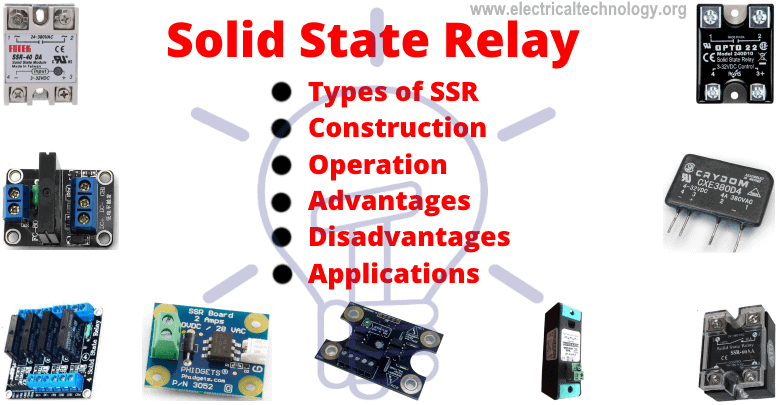
Solid State Relay: Types of SSR Relays – Construction and Operation
What is Solid State Relay? Construction, Operation, Applications and Types of SSR Relays
In this article, we will briefly discuss the SSR (Solid State Relay), its construction, operation, Schematics and different types of SSR relays based on its switching property and input/output forms. We will also discuss the advantages and disadvantages of Solid State Relay (SSR) comparing to Electromagnetic Relays (EMR) relay.
What is a Solid State Relay (SSR)?
Solid state relay (SSR) is an electronic switching device made of semiconductors that switch (On and Off) a high voltage circuit using a low voltage at its control terminals.
Unlike EMR (Electromagnetic relay) that has a coil and mechanical switch (physical contacts), the SSR relay uses Optocoupler to isolate the control circuit from the controlled circuit.
Schematic Model of SSR Relay
A general schematic for the operation of a DC to AC SSR relay’s operation with model schematic is given below:
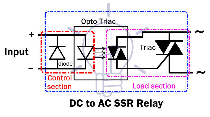
A DC input of sufficient voltage is applied at the control input terminals. There is a diode for protection against the reverse polarity of the applied DC.
When the voltage is applied to the LED of the optocoupler, it emits infrared light.
On the other end, the Opto-TRIAC (receiver) picks up the light and switches on. As soon as the optocoupler switches on, the output AC current starts flowing through it
In turn, this optocoupler’s output activates the TRIAC. Thus allowing the flow of AC Load Circuit current
Related Posts:
- Electromechanical Relay or Electromagnetic Relay (EMR – Types and Applications)
- Different Types of Relays, Their Construction, Operation and Applications
Difference Between SSR and EMR
The operation of SSR (Solid State Relay) and EMR (Electromagnetic or Electromechanical Relay) or contact relay is same while the main different between SSR and EMR is that there are no mechanical parts and contacts in SSR relay. Normally, SSR has 1a contact while EMR having multiple contacts.
Other different between Solid State Relay and Electromagnetic relay are that there is no surge and noise during the operation of SSR. There is a chance of leakage current about few μA to mA in SSR relay while the value of leak current is Zero (0) in EMR. At the other hand, SSR switch OFF AC loads at the point of 0 load current which leads to eliminate the noise, contact bounce and electrical arcing in case of inductive load as compared to EMR relays.
Related Posts:
- Difference Between Solid-State Relay and Electromechanical Relay
- Difference Between Relay and Circuit Breaker
Construction of SSR (Solid State Relay)
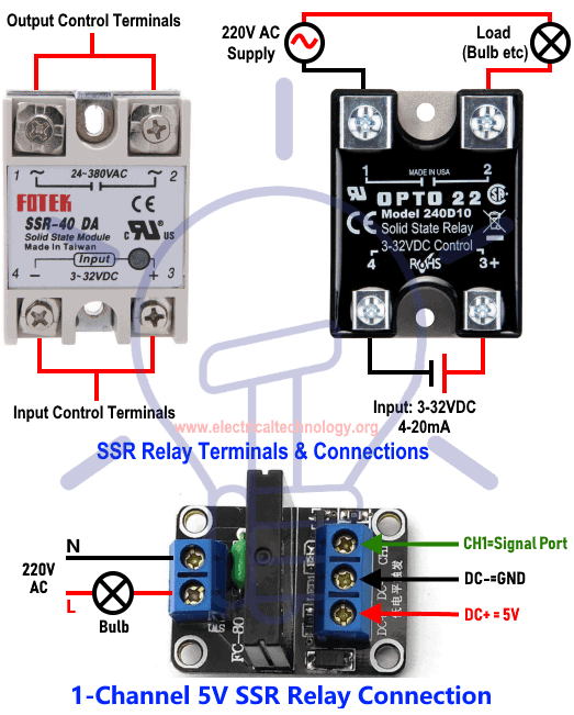
Terminals of SSR Relay
SSR relay has two sets of terminals i.e. input terminals and output terminals. These terminals are given below:
Input or Control Terminals
These two terminals are the input control terminal. It is connected to a low power circuit that controls its switching.
The control input of an SSR relay is designed for DC or AC circuit separately.
The Output Normally Open (NO) Terminals
The output terminals of SSR relay switches on and off depending on the control input.
Normally, the electrical connection between these terminals remains open. When the relay activates, these terminals connect together providing a closed path.
The output terminals are specifically designed for either AC or DC circuit. Unlike EMR relay, an SSR relay cannot switch both AC and DC signal using the same terminals.
Output Normally Closed (NC) Terminal
This terminal of the relay remains closed until the relay is activated. There is no current flow when the relay activates. It becomes open upon activation of the relay.
Related Posts:
- Types of Switches. Its Construction, Working and Applications
- Different Types of Sensors with Applications
Operation and Working of SSR Relay
When a low voltage is applied to the input control terminals of the SSR relay, the output Load terminals becomes electrically short.
The input of the SSR relay activates the optocoupler which switches the Load circuit. The optocoupler has no physical connection and it isolates the low voltage circuit from the high voltage circuit.

Optocoupler has an LED at its input which emits infrared light when a voltage is applied. These IR waves are received by the photo-sensor (Photo-transistor, photodiode etc.) on its output end. The Photo-sensor converts the light signal into an electrical signal and switches on the circuit.
To activate the optocoupler, its input voltage should be greater than its forward voltage. Due to this reason, SSR relays does not activate on lower voltage than its specified voltage.
The output circuitry of SSR relay varies for AC and DC circuits. It is usually made up of TRIAC or Thyristors for AC circuit and Power MOSFETs for DC circuit.
- Related Post: Types of Diodes and Their Applications
Types Of SSR Relay
There are different types of SSR (Solid State) relays. They are either classified on their Input/output form or their switching property.
Classification Based On Input/Output
Following are some of the common types of SSR relay classified based on its input and output circuit (AC/DC).
DC-To-AC SSR Relay
This relay Operates on DC input to switch an AC Load Circuit. The control input of this SSR relay only operate on DC input.
The fact that this relay does not operate on AC input is because optocoupler operate on DC. Its input terminals are also directional. Reversing the polarity of the input will not activate the relay. There is a diode used for protection against the reverse polarity of the input.
Even after applying the required input, the output switch of this SSR does not activate but only when AC voltage is applied to its output terminals.
Following is the schematic of a DC-TO-AC SSR relay.

Related Post: Types of Transformers and Their Applications
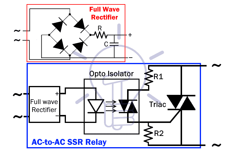
AC-To-AC SSR Relay
The SSR relay operates only when the Input and output both circuits are AC.
As we know, the optocoupler operates on DC voltage. So a rectifier is used before the optocoupler to convert AC into DC.
When sufficient AC voltage is applied to its input control terminal, it activates providing the flow of AC load current.
Its schematic is given below.
DC-To-DC SSR Relay
This relay can switch High power DC load using a low power DC source.
The DC input is applied to the optocoupler as described in the other example above.
However, to switch a DC load, a power MOSFET or IGBT is used.
The MOSFET conducts current in only one direction so it is also necessary to make sure the output load is connected using correct polarity. A protection diode is used to avoid damage during reverse polarity.
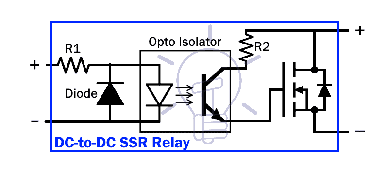
If there is an inductive load, a freewheeling diode should be used with the load.
DC-To-AC/DC SSR Relay
This type of SSR relay can switch AC and DC load using separate terminals.
Such kind of SSR relay uses MOSFETs in series with common Source terminals for switch both AC and DC circuit.
Its schematic is given below.
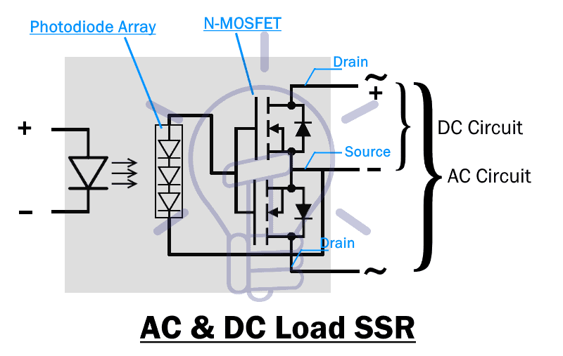
This schematic shows a photodiode cell array as a light sensor which produces a voltage when the LED activates. This voltage is applied to the gates and source of the N-MOSFETs connected in series.
To use this relay for AC circuit, the Drain terminals of MOSFETs are used and the source terminals should remain unused.
While using DC circuit, Drain and source terminal of the MOSFETs are used for switching.
Classification Based On Switching Property
SSR relays are also classified based on their switching properties which are given below.
These relays control AC circuits and are used for controlling the desired outputs in a specific application
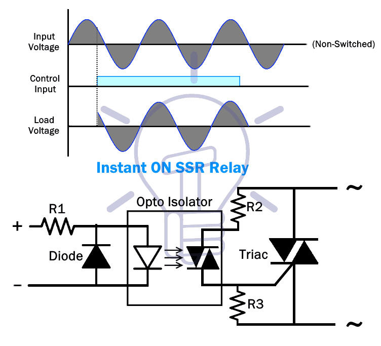
Instant ON SSR Relay
Such type of relay instantly switches on the load circuit whenever a sufficient input voltage is applied. It switches off upon the next zero crossing of load voltage after the removal of the control input.
Zero Switching SSR Relay
This kind of relay switches on when an input voltage is applied and the load AC voltage crosses the next zero voltage.
It turns off like normal SSR relays when the input voltage is removed and the load AC voltage reaches zero volts.
The operation for zero switching relay is achieved by a circuit known as zero crossing circuit, which detects the zero crossing and activates the TRIAC.

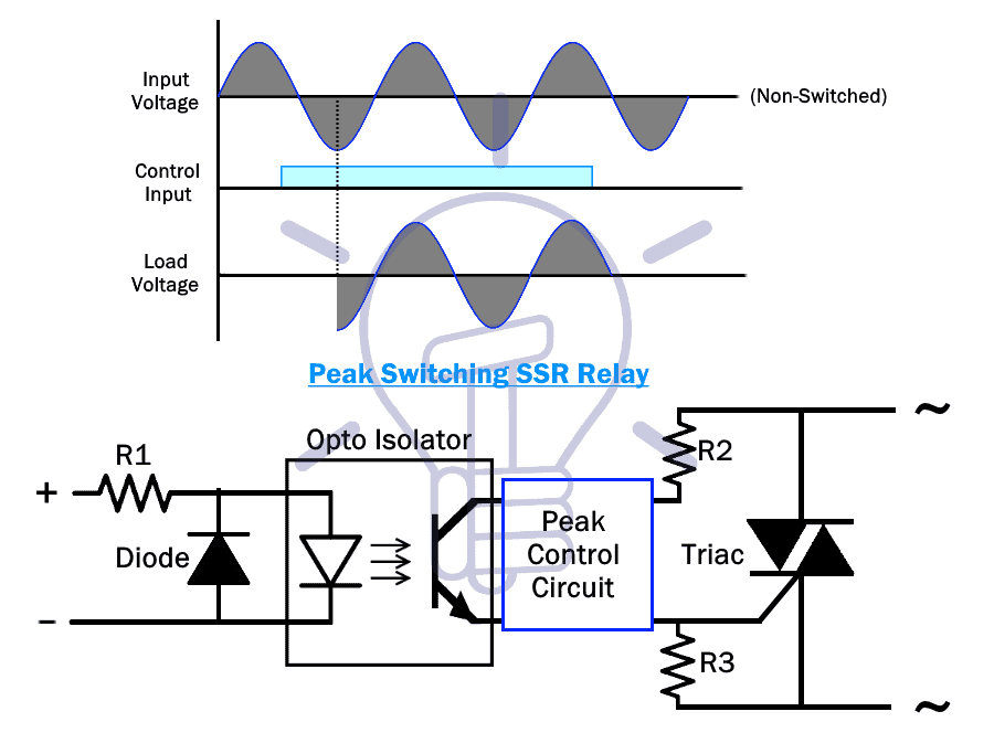
Peak Switching SSR Relay
These types of SSR relay switches on when the output AC voltage hits its next peak after applying the required input control voltage.
It also turns off after the removal of the input voltage and the zero crossing of the output AC current.
There is a peak detection block used in these relays, which fires the TRIAC when the output AC cycle hits its peak.
Analog Switching SSR Relay
While these other types of SSR’s switching depend on output AC cycle, this relay’s switching depends on its input amplitude.
The starting output voltage of analog SSR relay is proportional to the input control voltage.
Suppose 3-32v DC input relay’s 3v represents 0% and 32v represent 100% of the load AC peak voltage.
When the control input is removed the relay switches off upon the next output AC zero crossing.
Classification Based On Poles and Throw
SSR relays are classified into three types or “Forms” considering their poles and throw configuration.
Form A Or SPST NO Type SSR
Form A type of SSR relay is SPST (Single Pole Single Throw) relay with normally open (NO) terminals. The output load terminals are normally open when there is no external control input. When the relay activates, the output terminals connect together and allows the flow of current.
The diagram below shows an SSR relay capable of switching AC and DC on separate terminals.

A photodiode cell is used as a light receiver and enhancement MOSFETs with common sources are used for switching the load circuit.
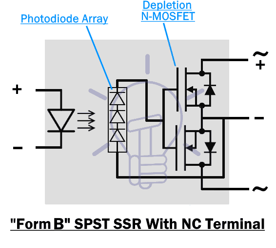
Form B Or SPST NC Type SSR:
Form B type of SSR relay has normally closed load terminals. The output load terminals are normally connected and allow current flow when there is no control input. Providing a control input will open the load terminals and stop the current flow.
This type of relay uses depletion MOSFETs which turn ON at zero input and turn off when its Vgs is negative.
The diagram below shows form B SPST NC relay using depletion MOSFETs.
Form C Or SPDT Type SSR:
Form C type of SSR relay has two switch throw terminals.
There are three load terminals i.e. Common, NC and NO.
When the relay is not active, the common terminal remains connected with the NC terminal.
When the relay activates, the common terminal connects to the NO terminal.
The diagram of SPDT SSR relay is given below.
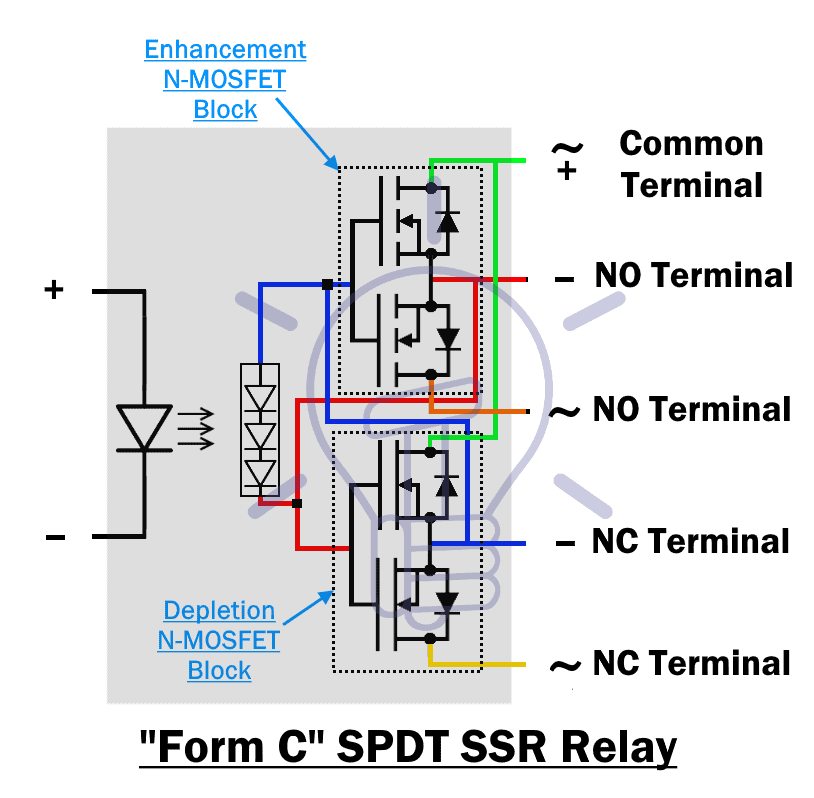
There is also a control switching circuit that prevents the MOSFETs from turning on at the same time by providing a time delay between its switching.
Advantages and Disadvantages
Advantages:
- SSR switching time is much faster than EMR (Electromechanical relay) relay.
- It has no physical contacts.
- There is no issue of contacts spark and wear out.
- They have a longer lifespan than EMR relays.
- SSR relay Switch off at 0 AC load current which prevents any arch or electrical noise.
- Vibrations or movement does not affect its operation.
- It has very low power consumption as compared to EMR relay.
- SSR relay is very easily controlled by logic circuits(microcontrollers)
Disadvantages
- It has a complex design as compared to EMR relay
- There is a voltage drop across its load terminals.
- It has a leakage current during off state.
- SSR relays dissipate too much heat.
- It cannot switch low voltages as compared to EMR relay.
- SSR relay switching depends on the voltage of the controlled circuit.
Related Post: Types of ICs. Classification of Integrated Circuits and Their Limitation
Applications of SSR (Solid State) Relays
Below are the common uses of Solid State Relays in the field of electrical and electronics engineering.
- Generally, SSR relay are used for switching purpose i.e. ON/OFF control of AC Power.
- It is used to control the power i.e. motor speed control, light and fan dimming, power switching etc.
- They are also use to drive electric heaters to control the temperature.
- SSR cab be used as a latch which is useful in case of kettles.
- In communication lines, photocoupler SSR relay are used to eliminate relay driving current flowing through it.
- Solid state relay are mostly used in High load switching.
Related Posts:
- How to Test a Relay? Checking SSR and Coil Relays
- What is a Solenoid and Solenoid Magnetic Field
- Air Circuit Breaker (ACB) – Construction, Operation, Types and Uses
- MCB (Miniature Circuit Breaker) – Its Construction, Working, Types and Uses
- MCCB (Molded Case Circuit Breaker) – Construction, Types and Working
- What is an RCD (Residual Current Device)? – RCB and RCCB
- ELCB (Earth Leakage Circuit Breaker) – Construction, Types & Working
- How to Wire an RCBO? Residual Current Breaker with Overcurrent
- What is a Contactor ? Types, Working and Applications
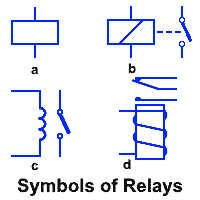
- Relay Symbols – Electrical and Electronic Symbols
Related Premium Resources for Wiring Installation for Relays in Different Circuits
- How to Reverse Operation of Photo Eye for Motor using Relay?
- How to Wire ST01 Timer with Relay & Contactor for 120V/240V Motors?
- How to Wire AH3 OFF-Delay Timer and Relay with Boiler Fan?
- Automatic Phase Reverse Protection Using Contactors & Relay
- ON / OFF 3- Phase Motor Using 14-PIN Relay and DOL Starter
- How to Wire 14-PIN Relay for Holding or Latching Circuit?
- ON / OFF 3- Phase Motor Using 11-PIN Relay and DOL Starter
- How to Wire 11-PIN Relay for Interlocking and Holding Circuits?
- ON / OFF 3- Phase Motor Using 8-PIN Relay and DOL Starter
- How to Wire 8-PIN Relay for Holding or Latching Circuit?
- How to Control a Three-Phase Motor Using Solid-State Relay?


Thanks.Great and brief TUTORIAL. Can they operate transformer loads efficiently? and please give the SSR numbers/POWER RATINGS.