What is Rectifier? Types of Rectifiers and their Operation
Different Types of Rectifiers – Working and Applications
In electronics, Rectifier circuit is the most used circuit because almost every electronic appliance operates on DC (Direct Current) but the availability of the DC Sources are limited such as electrical outlets in our homes provide AC (Alternating current). The rectifier is the perfect candidate for this job in industries & Home to convert AC into DC. Even our cell phone chargers use rectifiers to convert the AC from our home outlets to DC. Different types of Rectifiers are used for specific applications.
We mainly have two types of voltage types present that are widely used these days. They are alternating and direct voltage types. These voltage types can be converted from one type to another using special circuits designed for that particular conversion. These conversions happen everywhere.
Our main supply which we get from power grids are alternating in nature and the appliances we use in our homes generally require a small DC voltage. This process of converting alternating current into direct current is given the name rectification. Converting AC to DC is preceded by further process which can involve filtering, DC-DC conversion and so on. One of the most common part of an electronic power supply is a bridge rectifier.
Many electronic circuits require rectified DC power supply for powering various electronic basic components from available AC mains supply. The simple bridge rectifier is used in a variety of electronic AC based power devices.
Another way to look at the rectifier circuit is that, it can be said to convert currents instead of voltages. This makes more intuitive sense, because we are more accustomed to using current to define a component’s nature. Concisely, a rectifier take a current which has both negative and positive components and rectifies it such that only the positive component of the current remains.
Bridge rectifiers are widely used in power supplies that provide necessary DC voltage for the electronic component or devices. The most efficient switching devices whose characteristics are known fully are diodes. In theory any solid-state switch which can be controlled or cannot be controlled can be used instead of the diodes.
- Related Post: Types of Diodes and Their Applications
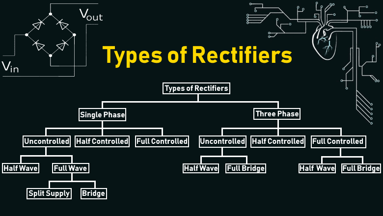
Usually, the types of Rectifiers are classified based on their output. In this article, we will discuss many types of Rectifiers such as:
- Single Phase Rectifiers
- Three Phase Rectifiers
- Controlled Rectifiers
- Uncontrolled Rectifiers
- Half Wave Rectifiers
- Full Wave Rectifiers
- Bridge Rectifiers
- Center-Tapped Rectifiers
What is Rectifier?
A Rectifier is an electrical device that is made of one or more than one diodes that converts the alternating current (AC) into direct current (DC). It is used for rectification where the process below shows that how it convert AC into DC..
What is Rectification?
Rectification is the process of conversion of the alternating current (which periodically changes direction) into direct current (flow in a single direction).
Types of Rectifiers
There are mainly two types of rectifiers:
- Uncontrolled Rectifier
- Controlled Rectifier
Bridge rectifiers are of many types and the basis for the classification can be many, to name a few, type of supply, bridge circuit’s configurations, controlling capability etc. Bridge rectifiers can be broadly classified into single and three phase rectifiers based on the type of input they work on. Both of these types include these further classifications which can be made into both single and three phase rectifiers.
The further classification is based on the switching devices the rectifier uses and the types are uncontrolled, half controlled and full controlled rectifiers. Some of the types of rectifiers are discussed below.
Based on the type of rectification circuit does, the rectifiers are classified into two categories.
- Half wave rectifier
- Full wave rectifier
Half wave rectifier only converts half of the AC wave into DC signal whereas Full wave rectifier converts complete AC signal into DC.
Bridge rectifier is the most commonly used rectifier in electronics and this report will deal with the working and making of one. Simple bridge rectifier circuit is the most popular method for full wave rectification.
We will discuss both the controlled and uncontrolled (half waves and full waves bridge) rectifiers in details with circuit diagrams and operation as follows.
- Related Post: Types of Transformers and Their Applications
Uncontrolled Rectifier:
The type of rectifier whose output voltage cannot be controlled is called an uncontrolled rectifier.
A rectifier uses switches to work. The switches can be of various types, broadly, controllable switches and uncontrollable switches. A diode is unidirectional device that allows the current flow in only one direction. The working of a diode is not controlled as it will conduct as long as it is forward biased.
With a configuration of diodes in any given rectifier, the rectifier is not fully in the operator’s control, so these types of rectifiers are called uncontrolled rectifiers. It does not allow the power to vary depending on the load requirement. So this type of rectifier is commonly used in constant or fixed power supplies.
- Related Post: Filters, Types of Filters and Their Applications
Uncontrolled rectifier uses only diodes and they give a fixed output voltage depending only on the AC input.
Types Of Uncontrolled Rectifier:
Uncontrolled Rectifiers are further divided into two types:
- Half Wave Rectifier
- Full Wave Rectifier
Half Wave Rectifier:
A Type of rectifier that converts only the half cycle of the alternating current (AC) into direct current (DC) is known as halfwave rectifier.
- Positive Half Wave Rectifier:
A half wave rectifier that converts only the positive half cycle and blocks the negative half cycle.
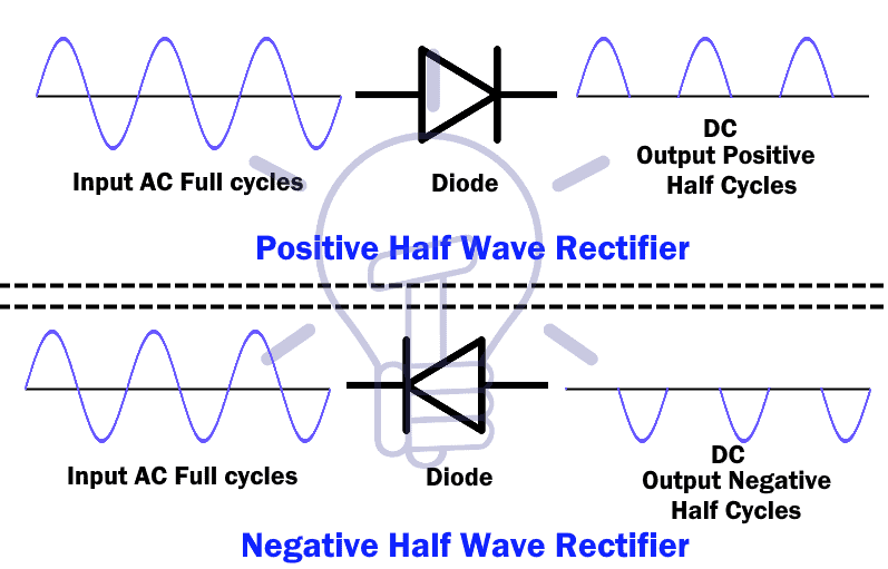
- Negative Half Wave Rectifier:
A negative half wave rectifier converts only the negative half cycle of the AC into DC.
In all types of rectifiers, a half-wave rectifier is the simplest of them all as it is composed of only a single diode.

A diode allows the current flow in only one direction known as forward bias. A load resistor RL is connected in series with the diode.
- Related post: Different Types of Sensors with Applications
Positive Half Cycle:
During the positive half cycle, the diode terminal anode will become positive and the cathode will become negative known as forward bias. And it will allow the positive cycle to flow through.

Negative Half Cycle:
During the negative half cycle, the anode will become negative and the cathode will become positive, which is known as reverse bias. So the diode will block the negative cycle.
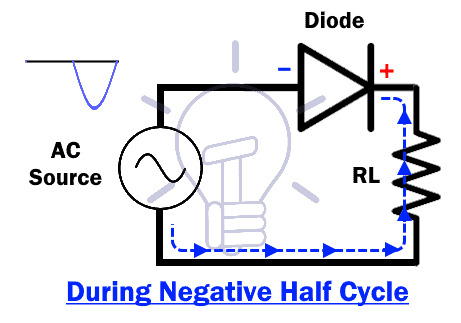
So when an AC source is connected to the half-wave rectifier, only half cycle will flow through it as shown in the figure below.

The output of this rectifier is taken across the load resistor RL. if we look at the input-to-output graph, it shows a pulsating positive half cycle of the input.
The output of the half wave rectifier has too many ripples & it is not very practical to use this output as DC source. To smooth this pulsating output, a capacitor is introduced across the resistor. The capacitor will charge during the positive cycle and discharge during the negative cycle to give out a smooth output signal.
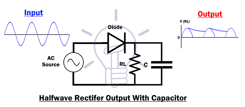
Such types of rectifiers waste the power of AC input’s half cycle.
Full Wave Rectifier:
A full wave rectifier converts both positive and negative half cycles of the AC (alternating current) into DC (direct current). It provides double output voltage compared to the halfwave rectifier
A full wave rectifier is made up of more than one diode.
There are two types of full wave rectifier.
- Bridge Rectifier
- Center-Tap Rectifier
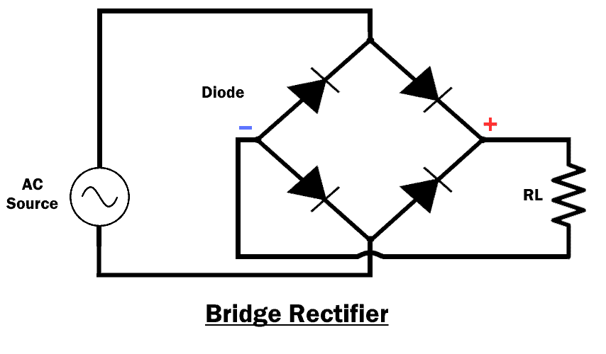
Bridge Rectifier
A bridge rectifier uses four diodes to convert both half cycle of the input AC into DC output.
In this type of rectifier, the diodes are connected in a specific form as given below.
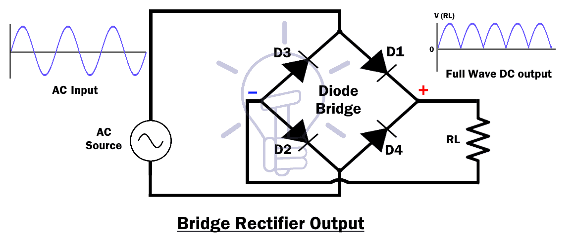
Positive Half Cycle:
During input positive half cycle, the diode D1 & D2 becomes forward bias while D3 & D4 becomes reverse bias. The diode D1 & D2 form a closed loop that provides a positive output voltage across the load resistor RL.

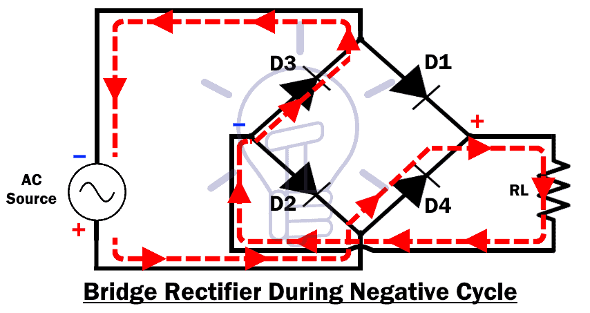
Negative Half Cycle:
During the negative half cycle, the diode D3 & D4 becomes forward bias while D1 & D2 becomes reverse bias. But the polarity across the load resistor RL remains the same and provides a positive output across the load.
The output of full wave rectifier has low ripples compared to half-wave rectifier but still, it’s not smooth and steady.
In order to make the output voltage smooth & steady, a capacitor is placed at the output as shown in the figure below.

The capacitor charge & discharges which make smooth transitions between the half cycles.
Working of Bridge Rectifier Circuit
From the circuit diagram it is apparent that the diodes are connected in a particular fashion. This unique arrangement gives the converter its name. In bridge rectifier, voltage that is given as the input can be from any source. It can be from a transformer that is used to step up or down the voltage or it can be from the mains of our domestic power supply. In this article, we are using a 6-0-6 center-tapped transformer for providing AC voltage.
In the first phase of working of the rectifier, during the positive half cycle, diodes D3-D2 get forward biased and conducts. Diodes D1-D4 gets reversed biased and do not conduct in this half cycle, acting as open switches. Thus, we get a positive half cycle at the output. Conversely, in the negative half cycle, diodes D1-D4 get forward biased, and start conducting whereas diodes D3-D2 gets reversed biased and do not conduct in this half cycle.
- Related Post: Types of Inductors and Their Applications
Again, we get a positive half cycle at the output. At the end of the rectification process, the negative part of the AC current is converted into a positive cycle. The output from the rectifier is two half-positive pulses with the same frequency and magnitude as that of the input.
In contrast to the working of a half-wave rectifier, the full bridge rectifier has another branch which allows it to conduct for the negative half of the voltage waveform which the half-bridge rectifier had no means of doing. So the average voltage at the output of the full bridge rectifier is double than that of the half-bridge rectifier.
Although we use four individual power diodes to make a full wave bridge rectifier, pre-made bridge rectifier components are available “off-the-shelf” in a range of different voltage and current sizes that can be used directly to make a working circuit.
The output voltage waveform after the rectification is not a proper DC, so we can try to make it more into a DC waveform using a capacitor for filtering purpose. Smoothing or reservoir capacitors that are connected in parallel with the load across the output of the full wave bridge rectifier circuit increases the average DC output level to the required average DC voltage at the output because the capacitor not only acts as a filtering component, but it also periodically charges and discharges effectively increasing the output voltage.
Capacitor charge till the waveform goes to its peak and discharges uniformly into the load circuit when waveform starts going low. So when the output is going low, capacitor maintains the proper voltage supply into the load circuit, hence creating the DC.
- Related Post: Types of Batteries and Cells and Their Applications
Advantages of a Bridge Rectifier:
- Low ripples in the output DC signal
- High rectifier efficiency
- Low power loss
Disadvantages of Bridge Rectifier:
- Bridge rectifier is more complex than a half-wave rectifier
- More power loss compared to canter-tapped full wave rectifier.
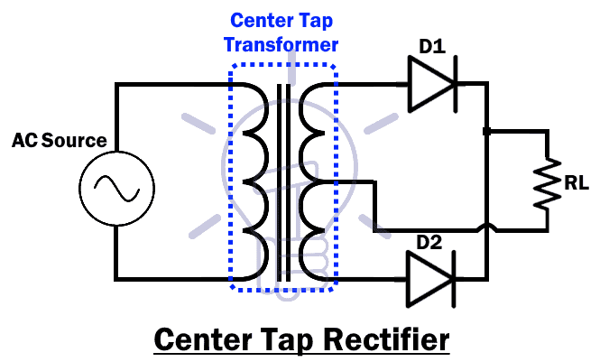
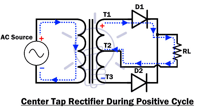
Center-Tap Rectifier
This type of full-wave rectifier uses a center-tap transformer & two diodes.

A center-tap transformer is a dual-voltage transformer that has two inputs (I1 & I2) and three output terminals (T1, T2, T3). The T2 terminal is connected to the center of the output coil which acts as a reference ground (o volt reference). The T1 terminal produces positive voltage and the T3 terminal produces negative voltage with respect to the T2.
The design of the center-tap rectifier is given below:
Positive Half Cycle:
During the input positive half cycle, the T1 will produce positive and T2 will produce a negative voltage. The diode D1 will become forward bias & diode D2 will become reverse bias. This makes a close path from T1 to T2 through the load resistor RL as shown below.
Negative Half Cycle:
Now during the input negative half cycle, T1 will generate negative cycle & T2 will generate a positive cycle. This will put the diode D1 into reverse bias & diode D2 in forward bias. But the polarity across the load resistor RL is still the same as the current takes the path from T3 to T1 as shown in the figure below.

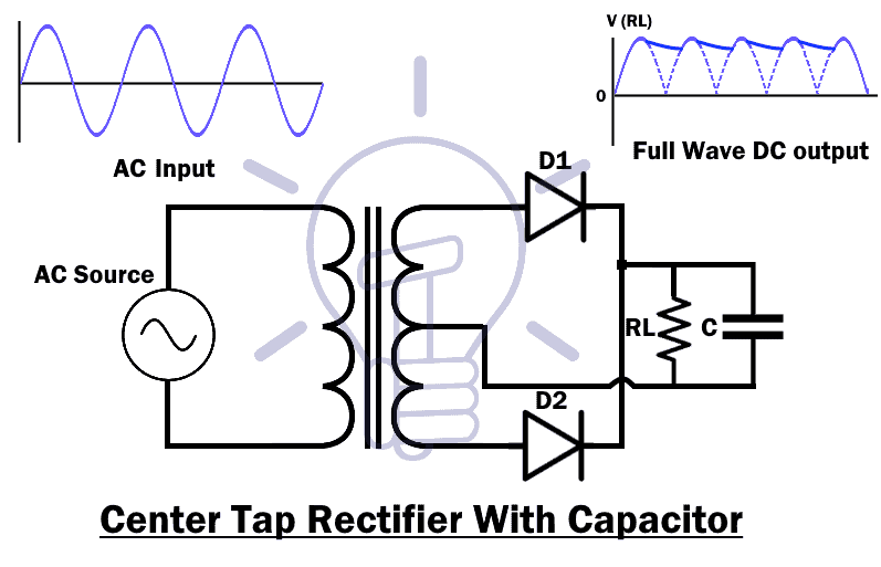
The DC output of a center-tap rectifier also has ripples and it’s not smooth & steady DC. A capacitor at the output will remove the ripple and make a steady DC output.
Controlled Rectifier:
A type of rectifier whose output voltage can be varied or changed is called controlled rectifier.
The need for a controlled rectifier is apparent when we look into the shortcomings of an uncontrolled bridge rectifier. To make an uncontrolled rectifier into a controlled one we use current-controlled solid-state devices such as SCRs, MOSFETs, and IGBTs. We have the full control when SCRs are switched ON or OFF based on the gate pulses we apply to it. These are generally more preferred than their uncontrolled counterparts.
It is composed of one or more than one SCR (Silicon Controlled Rectifier).
An SCR, also known as thyristor is a three-terminal diode. These terminals are Anode, Cathode & a control input known as Gate.
Just like a simple diode an SCR conduct in forward bias and blocks current in reverse bias but it only starts forward conduction when there is a pulse at the gate input. So the output voltage can be controlled using the gate input.
Types of Controlled Rectifiers
There are two types of controlled rectifier.
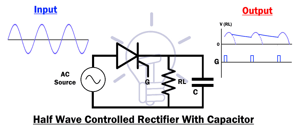
Half Wave Controlled Rectifier
The half wave controlled rectifier is made up of a single SCR (Silicon Controlled Rectifier).
Half wave controlled rectifier has the same design as the half wave uncontrolled rectifier except we replace the diode with an SCR as shown in figure down below.

An SCR does not conduct in reverse bias, so it will block the negative half cycle.
During the positive half cycle, the SCR will conduct current on one condition when a pulse is applied to the gate input. The gate input is, of course, a periodic pulse signal which is designed to activate the SCR at each positive half cycle.
In this way, we can control the output voltage of this rectifier.
- Related Post: Counter and Different Types of Electronic Counters
The output of the SCR is also a pulsating DC voltage/current. These pulses are removed by using a capacitor parallel to the load resistor RL.
Full Wave Controlled Rectifier
A type of rectifier that converts both positive and negative half cycle of the AC into DC as well as controls the output amplitude is known as a full wave controlled rectifier.
Just like uncontrolled rectifier, controlled full wave rectifier has two types.
- Related Post: Types Of Capacitors | Fixed, Variable, Polar & Non-Polar
Controlled Bridge Rectifier
In this rectifier, the diode bridge is replaced by an SCR (Thyristor) bridge with the same configuration as shown in the figure below.
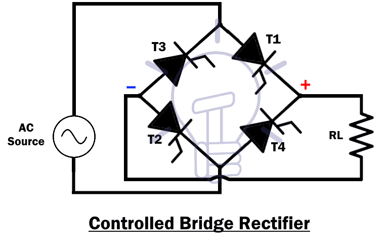
Positive Half Cycle:
During the positive cycle, the SCR (thyristor) T1 & T2 will conduct when the gate pulse is applied. T3 & T4 will be reversed bias, so they will block the current. The output voltage will be established across the load resistor RL as shown below.

Negative Half Cycle:
During the negative half cycle, the thyristor T3 & T4 will become forward bias considering the gate input pulse & the T1 & T2 will become reverse bias. The output voltage will appear across the load resistor RL.

At the end of the output, a capacitor is used to remove the ripples and makes the output steady & smooth.

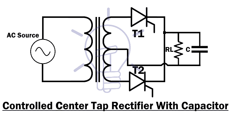
Controlled Center-Tap Rectifier:
Just like center-tap uncontrolled rectifier, this design uses two SCR replacing the two diodes.
Both of these SCR switching will be timed differently according to the input AC frequency.
Its operation is the same as the uncontrolled rectifier & its schematic design is given below.
- Related Post: Types of Latches – SR & D Latches
Single Phase and Three Phase Rectifiers
This classification is based on the type of input a rectifier works on. The naming is pretty straightforward. When the input is single phase, the rectifier is called a single phase rectifier and when the input is three phase, it is called a three phase rectifier.
The single phase bridge rectifier consists of four diodes, whereas a three phase rectifier uses six diodes arranged in a particular fashion to get the desired output. These can be controlled or uncontrolled rectifiers depending on the switching components used in each rectifier such as diodes, Thyristors, and so on.
Comparison of Rectifiers
The following table shows the compassion between different types of rectifiers such as half wave rectifier, full wave rectifier and center tapped rectifier.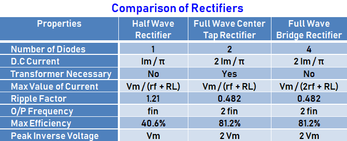
Applications Of Rectifiers
Basically, almost all electronic circuits operated on DC voltages. The main purpose of using rectifier is for rectification which means converting AC voltages to DC Voltages. Its mean, rectifiers are used in almost all power rectification and electronics appliances.
Below is the list of common applications and uses of different Rectifiers.
- Rectification i.e. converting DC Voltages to AC Voltages.
- Rectifiers are used in electric welding to provide the polarized voltage.
- It is also used in traction, rolling stock and three phase traction motors used for running trains.
- Half wave rectifiers are used in mosquito repellent and soldering iron.
- Half wave rectifier also used in AM Radio as a detector and signal peak detector.
- Rectifiers also used in modulation, demodulation and voltage multipliers.
Related Posts:
- Types of Transistors – BJT, FET, JFET, MOSFET, IGBT & Special Transistors
- Types of Inverters and their Applications
- Types of Active High Pass Filter
- Types of Passive High Pass Filters
- Types of Active Low Pass Filters
- Types of Passive Low Pass Filters
- Types of DEMUX – Demultiplexer Applications
- Types of MUX – Digital Multiplexer Applications
- Types of Binary Adders & Subtractor
- Types of Binary Encoder
- Types of Binary Decoder
- Types of Computer Memory with their Applications
- Types of Microprocessors & their Applications
- Types of Microcontrollers & their Applications
- Types of Thermistors and Applications
- Types of Transducers and Applications
- Types of Electrical Wires and Cables
- Types of Motor Starters and Motor Starting Methods
- Types of Circuit Breakers – Working and Applications
- Types of Fire Alarm Systems and Their Wiring Diagrams


Thanks for a detailed post on Rectifiers