Binary Encoder – Construction, Types & Applications
Digital Binary Encoder – Types & Construction
What is Binary Encoder?
A combinational circuit capable of converting “2n” input signals into “n” signals (such as BCD (Binary Coded Decimal) Binary etc) is called binary encoder also known as digital encoder.. Its operation is exactly opposite of Binary Decoder. In simple words, Binary Encoder used to encode a Binary Codes.
It has 2n input lines and “n” output lines. When we want to process data received from many data lines and we have few available input ports or we want to conserve the input ports of a system then we apply an encoder to reduce the number input data lines. Block diagram of binary encoder is given below.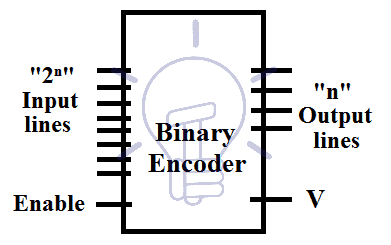
Line encoders are an example of Encoder in which multi-input lines are converted into a few binary outputs.
In line-encoders, one input at a time has a HIGH value otherwise the output will be invalid. Each data input line is treated as a single digit, for each line a specific binary output is generated in line encoders.
To clarify the problem of having more than one input line “HIGH”, priority encoders are used. Priority Encoders prioritize the input based on the design like in Line encoders, Most significant value out of the two inputs will decide the output. There is also an input condition check “V” which is low when there is no high input. And it is high when there is at least one high input.
Types of Binary Encoder
Some of the Line encoders are given below with details.
- 2-to-1 Line Binary Encoder
- 4-to-2 Line Encoder
- 4 to 2 Priority Encoder
- 8-to-3 Line Encoder
- 8 to 3 Priority Encoder
Also read: Counter and Types of Electronic Counters
Some of the line encoders are given below:
2 to 1 Line Encoder
Schematic & Truth Table
Simplest line encoder is 2 to 1 line encoder in which there are 2 input lines and 1 output line. 2 to 1 line Encoder schematic and truth table are given below.
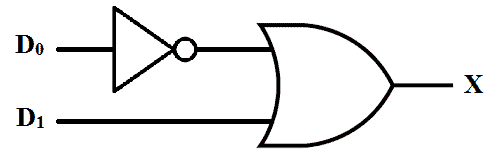
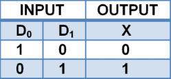
When D0 is high, the output is 0 and when D1 high output is 1 considering the other input is 0.
4 to 2 Line Encoder
This encoder has 4 input lines and 2 output lines. A single input line can be high at a time otherwise the output will be ambiguous. Block diagram of 4 to 2 line binary encoder is given below.
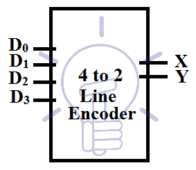
The output is in binary format. Each input line gives a combination of binary output.
Consider D0-D3 as 4 inputs and X, Y as output bits.
Truth Table
The truth table of 4-2 Encoder is given below:
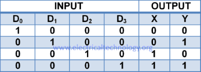
According to the truth table of 4 to 2 encoder:
X = D2 + D3
Y = D1 + D3
As from the above expressions, we deduce that binary encoder only needs OR gates. This encoder can be implemented with 2 OR gates as shown in the figure below. Schematic diagram of 4 to 2 line encoder using or gates it given below.
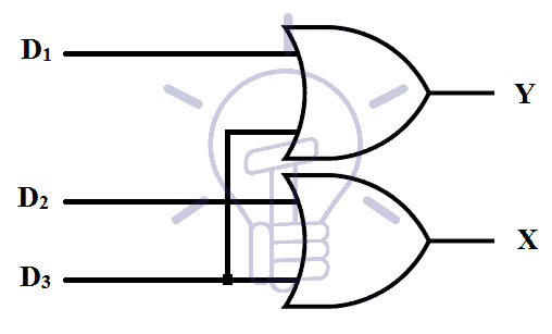 However, there is a limitation, when D1 and D2 are high at the same time then the output will be 1 1, which neither represent D1 nor D2 output. To remove this ambiguity, Priority encoders are designed.
4 to 2 Priority Encoder
This encoder prioritizes the highest input and produces output for that highest priority input regardless of the value of the other inputs. This encoder will prioritize D3 over D2,D1, and D0. D0 being the lowest priority input.
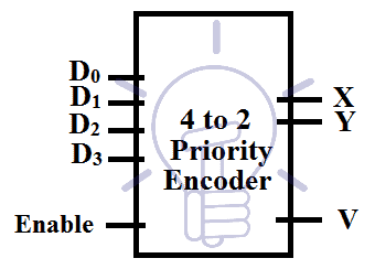
If D2 input is high then the output will be 10 whether the D1 input is low or high. There is input condition check “V” to make sure there is any input. “V” is high when there is any input.
Input and output variable are “D0-D3” and “X, Y, V” respectively.
Truth Table and K-Map
The truth table and K-Map for 4 to 2 priority encoder is:
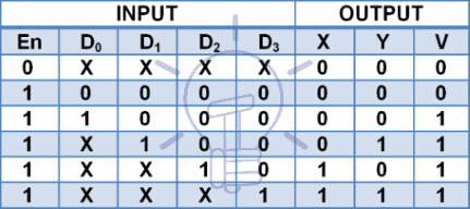
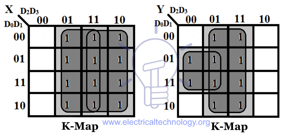
Using K-map solution:
X = D2 + D3
Y = D1D̅2 + D3
V = D0 + D1 + D2 + D3
These expressions are same as the normal encoder but there is a condition that Y = 1 for D1 only when D2 (higher priority than D1) is low because for D2 =1, “Y” should be “0” according to the truth table.
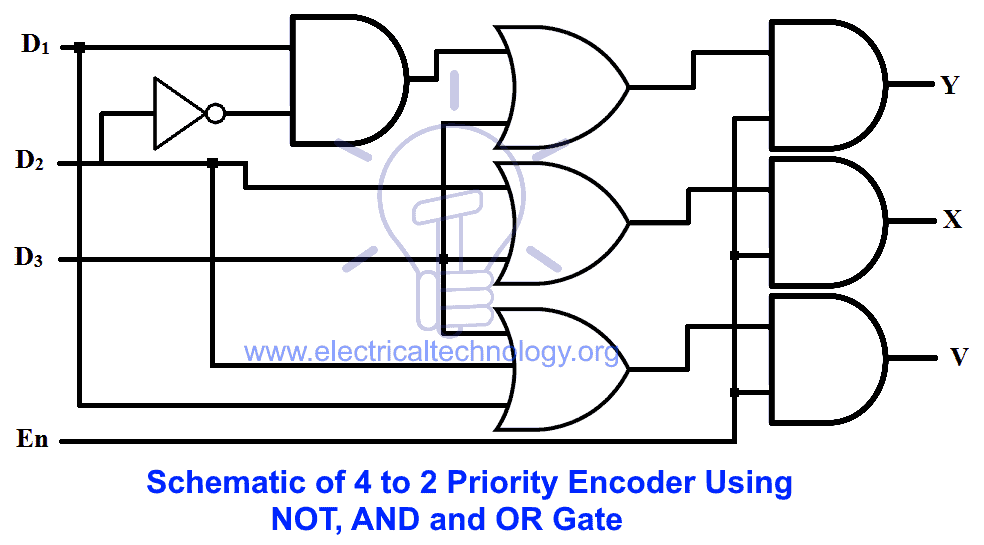
Schematic of 4 to 2 Priority Encoder
Schematic of priority encoder using NOT, AND and OR gate is given below.
8 to 3 Line Encoder
This encoder has 8 input lines and 3 output lines. It converts the octal into a binary system that is why it is known as octal to binary converter.
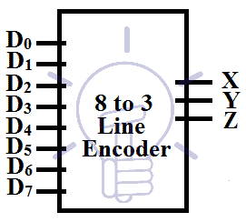
Consider D0-D7 as input and X,Y, Z as output.
Truth Table
The truth table for 8 to 3 line encoder is given below:
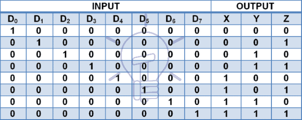
According to the truth table :
X = D4 + D5 +D6 + D7
Y = D2 + D3 +D6 + D7
Z = D1 + D3 +D5 + D7
- Also read: Ripple Carry And Carry Look Ahead Adder
8 to 3 Line Encoder Schematic Using OR gate
Schematic of 8 to 3 line encoder using OR gate is given below.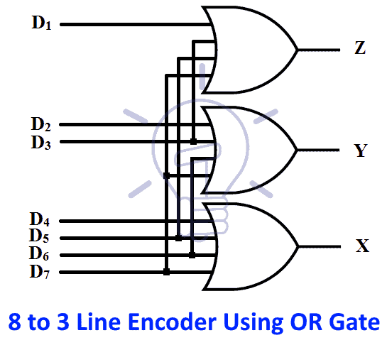
8 to 3 Priority Encoder

Consider D0-D7 as input and X,Y, Z as output and V as input condition check.
Truth Table
The truth table for 8-3 priority encoder is given below.

According to the truth table :
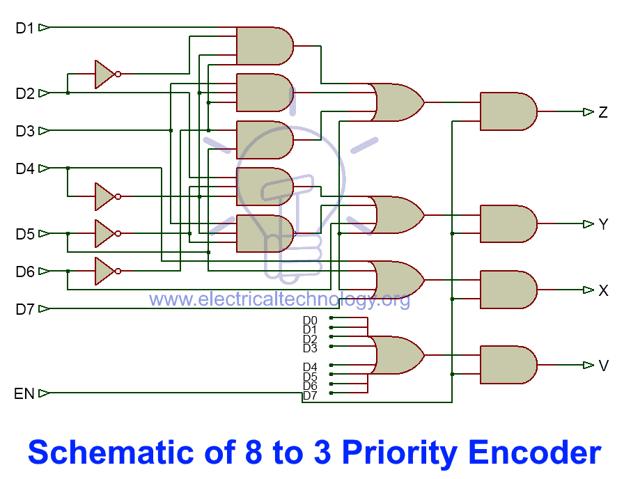
X = D4 + D5 + D6 + D7
Y = D2 D̅4 D̅5 + D3 D̅4 D̅5 + D6 + D7
Z = D1 D̅2 D̅4 D̅6 + D3 D̅4 D̅6 + D5 D̅6 + D7
V = D0 + D1 + D2 + D3 + D4 + D5 + D6 + D7
“X” being the MSB of binary output is high when any of D4,D5,D6 and D7 is high.
“Y” is high when D7 or D6 is high. It is also high when D3 or D2 is high considering D4 and D5 are low because if they are high then the output Y=0.
“Z” is high whenever D7 is high, it is also high when D1,D3,D5 are high but with these inputs other high priority input should be checked for which output “Z” goes low such as;
For D1; D2,D4,and D6 has to be low,
For D3; D4 and D6 has to be low,
For D5; D6 has to be low.
If any of them are high the output “Z=0″
8 to 3 Priority Encoder Schematic
Schematic of 8 to 3 priority encoder is given below.
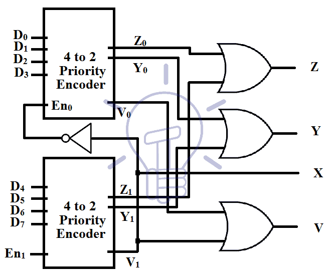
Cascading 4 to 2 Priority Encoders
8 to 3 priority encoder can be made by cascading 4 to 2 priority encoder with enable inputs.
When enable input is high the encoder is enabled
Inputs to the encoders are D0-D3 for first encoder and D4-D7 for the second encoder. The output of the first encoder is Y0, Z0 and second encoder output is Y1, Z1. Input condition check for the first decoder is V0 and second is V1.
Truth Table
The output of the whole 8 to 3 priority encoder is X, Y, Z. so the truth table would be:
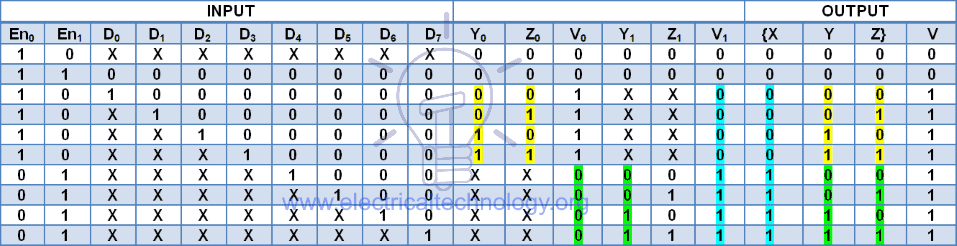
According to the truth table:
X = V1
Y = Y0 + Y1
Z = Z0 + Z1
V = V0 + V1
En0 = V̅1
when there is no input to the higher priority Encoder the lower Priority encoder will turn on.
- Also read: Comparator and Digital Magnitude Comparator
Schematic Diagram & Operation
Cascading 4 to 2 Priority Encoders implementation diagram is given below.
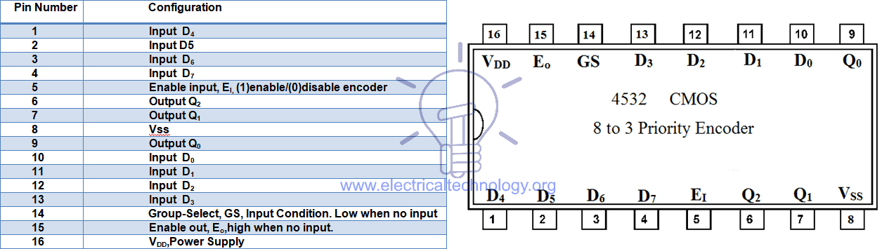
Binary Decoder IC Pinout
CMOS IC 4532 Priority Encoder
A CMOS IC 4532 Priority encoder’s pin configuration and details are given below.
Applications of Binary Encoders
Encoders are widely used in digital electronic systems. Some of common application and uses of encoders are as follow:
- In calculators, Encoders are used to encode the decimal values in binary to perform specific binary functions like addition, subtraction, multiplication and division etc.
- Encoders also used to generate digital signal (shaft encoders and linear encoders).
- Priority encoders are used to reduced the number of connection and wires in specific electronic circuit or applications with multiple inputs such as Keyboard (104 keys (as input) of a standard QWERTY keyboard) and Keypads as well as they are used to detect interrupts in microprocessor applications.
- The diode matrix encoders are used in printed circuit boards (PCB) on many electronic devices having keyboards as user data interface.
- Positional Encoders are used in magnetic positional control for positioning in robotic arms and ship navigation.
You may also read:


