How to Wire a Smart Dimmer Switch Companion with a Smart / Digital Dimmer for Multi-location Dimming
What is a Smart Dimmer Switch Companion?
A smart dimmer switch companion (also called an add-on or remote switch) is an auxiliary control device designed to work in conjunction with a primary smart or digital dimmer. They are used with a primary smart dimmer / switch for dimming light and fan speed control from additional locations.
Unlike a conventional 3-way mechanical switch, the companion does not directly switch the load. Instead, it communicates with the main dimmer through a traveler conductor, which sends low-voltage signaling commands to control ON/OFF and dimming functions from multiple locations.
Smart devices for smart home automation are available from different manufacturers such as Leviton, Legrand, and Lutron etc. The smart dimmer companion is specifically designed to operate only with compatible master dimmers and smart switches . It cannot function as a standalone dimmer and must always be paired with the designated smart or digital dimmer model.
The primary purpose of a smart dimmer companion is to enable multi-location dimming control. Using the companion switches in a multi-way wiring allows users to adjust brightness levels and switch lighting ON or OFF from two or more wall locations without complex rewiring or traditional 4-way switching circuits.
Smart Multi-Way Control Circuit
In a traditional 3-way or 4-way lighting circuit (Conventional Method), mechanical switches interrupt the line (hot) conductor. Two traveler wires carry the switched hot between devices. Dimming from multiple locations is not practical without specialized multi-way dimmers or 4-way (intermediate switches). This setup works well for basic ON/OFF control i.e. manual operations.
For smart control and dimming system, the primary smart dimmer is installed in the box where line (hot), load, neutral, and ground are available. The companion dimmer is installed in the secondary location(s).
Instead of switching line voltage, the companion sends digital or analog control signals to the primary dimmer via a designated traveler/control conductor. The main dimmer performs the actual load switching and dimming.
In smart multi-location control, the load is connected only to the primary dimmer. The traveler functions as a communication conductor (not as a traditional traveler carrying switched hot) and dimming levels are synchronized across all control points. A neutral conductor is typically required in the primary box (and sometimes in companion boxes depending on the design).
Using smart devices for multi-location control reduces complex 4-way wiring, mechanical switching stress and allows smart features such as, scene control, fade rates, soft start, remote/app-based control and voice assistant integration.
Good to Know: The smart dimmer companion switch is used for 3-way or multi-way switching only. A primary smart or digital switch, dimmer or fan speed controller device is prerequired to the control the load.
Wiring Smart Dimmer Switch Companion for 3-Way with & without Neutral
In this wiring guide, we demonstrate how to wire smart dimmer companion switches with compatible primary smart devices to control the same light or load from multiple locations.
The wiring diagrams are provided for 3-way wiring installation in different scenarios, such as:
- Neutral present in all switch boxes
- Neutral present in only one switch box
- Installations without a neutral conductor
For this guide, we use the Leviton DD0SR-DLZ smart dimmer companion in combination with a compatible Leviton smart switch (D315S / D215S, or digital dimmer (DW6HD/DH6HD/D26HD/D36HD) or DDL06/DD00R-DL) to illustrate proper multi-location wiring configurations.
Before starting, always disconnect power at the circuit breaker or main breaker in 120/240V panel and verify absence of voltage using a multimeter before performing any electrical work.
Step 1: Identify the Primary (Master) Location
Choose the box that contains:
- Line (Hot) conductor from the breaker
- Load conductor going to the light fixture
- Neutral (if required by manufacturer or circuit design)
- Ground
The primary smart/digital dimmer must be installed here.
Step 2: Identify the Companion Location
The second location typically contains:
- Traveler(s)
- Possibly Neutral
- Ground
The companion will replace the traditional 3-way switch (or 2-way in absence of neutral wire).
Step 3: Wiring the Smart/Digital Dimmer (Primary)
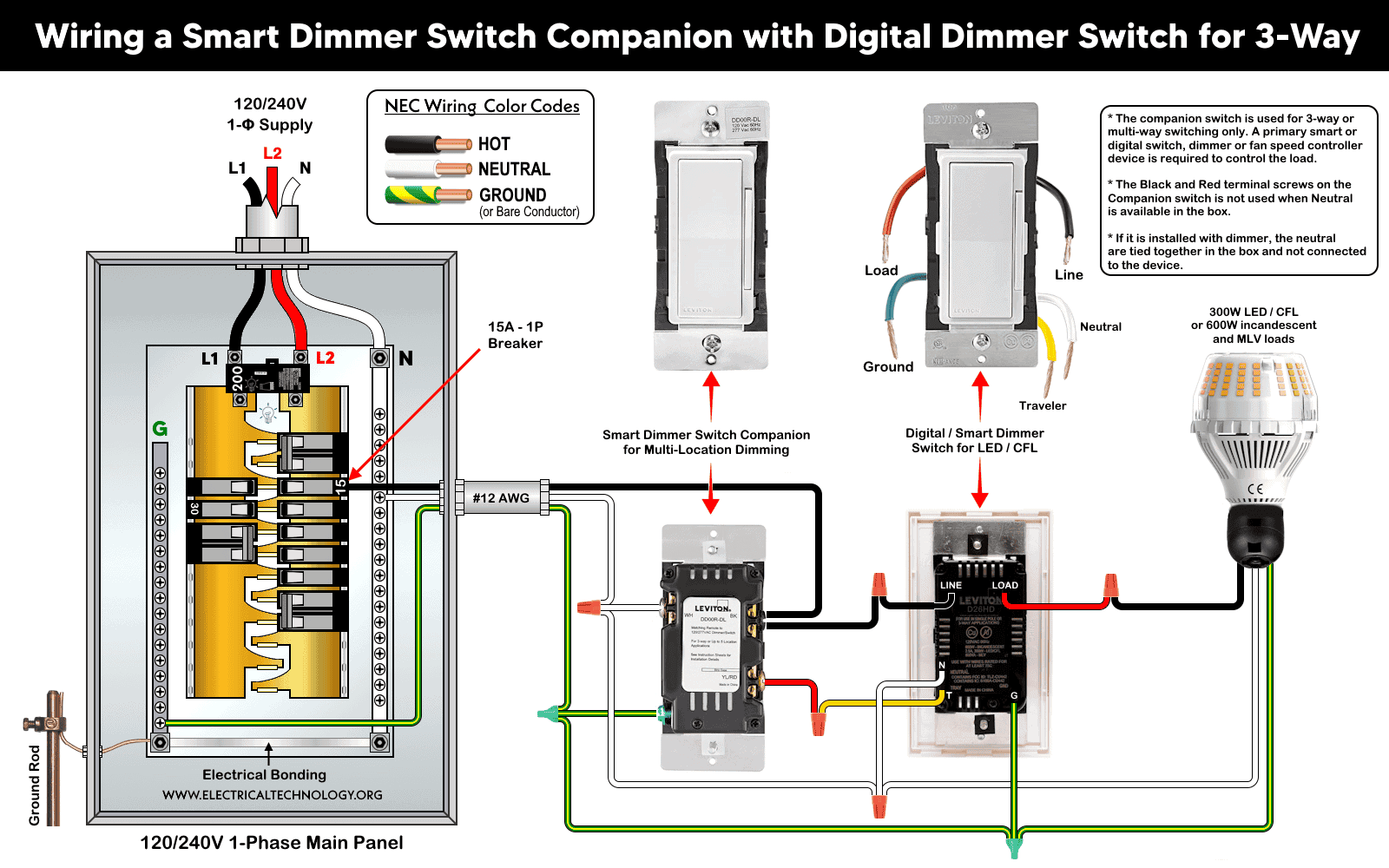
Connect the smart dimmer switch in the box 1 as follows:
- Line (Hot) as black wire (from companion circuit) to dimmer LINE “BK” terminal.
- Load as red and black to to dimmer LOAD terminal.
- Neutral as white wire to dimmer (WH terminal) for NEUTRAL – (if required).
- Traveler/Control wire to designated “YL/RD” terminal. from smart companion switch / dimmer
- Ground – equipment grounding conductor to the “G” terminal.
Cap any unused travelers and conductors in the box as per the manufacturer instructions.
Step 4: Wiring the Smart Dimmer Companion
At the companion location (i.e. box 2):
- Connect the Line (Hot) as black wire (from branch circuit) to companion switch LINE “BK” terminal.
- Connect the Traveler/Control conductor from primary device to companion’s control “YL/RD” terminal.
- Connect the Neutral (if required) from branch circuit of neutral bundle in the box to the “WH” terminal.
- Connect Ground as grounding conductor to the ground terminal.
Wiring diagram of a smart dimmer switch companion (DD0SR-DLZ) with a built-in LED locator, wired with a smart dimmer / switch (D26HD or D215S) for 3-way control.
Click image or open in a new tab to enlarge
Warning:
- Do NOT connect line or load to the companion unless explicitly specified by the manufacturer.
- The companion does not directly energize the load, it only transmits control signals to the primary smart device.
Step 5: Test & Configure
- Restore the breaker.
- Verify ON/OFF operation from both locations.
- Test dimming functionality from each device.
- Pair the primary smart dimmer with the manufacturer’s app (if applicable).
- Confirm synchronization of brightness levels across all locations.
Adding Additional Smart Dimmer Switch Companions for Multi-Way Control
If a neutral wire is present in next switch boxes, you may use four to nine smart switch companion devices with a compatible primary smart switch or digital dimmer to control a light from different locations.
If a neutral wire is not available at the companion location, you may use smart dimmer and companion model (such as Leviton DDL06 as shown in below wiring diagrams).
After wiring the primary device and the first companion, all additional companion switches are connected to the same line, neutral, traveler, and ground conductors using the identical wiring configuration shown above. This arrangement is commonly used in installations requiring more than two control points, such as a hallway with three or four switch locations.
To add additional companion switches, extend the Line (Hot), Neutral, Traveler, and Ground conductors through each switch box.
At every additional companion location:
- Connect Line (Hot) to the companion’s Line terminal.
- Connect Neutral to the Neutral terminal.
- Connect Traveler to the Traveler terminal.
- Connect Ground to the grounding terminal.
Verify that each companion device is energized and properly communicating with the primary switch or dimmer.
If your existing wiring does not match the diagrams above, or if the conductors in the box differ (for example, line feed at the luminaire or non-standard cable configurations), consult a qualified electrician. Incorrect wiring can result in electric shock, equipment damage, or fire hazards.
Wiring Diagrams for 3-Way Control Using Smart Devices
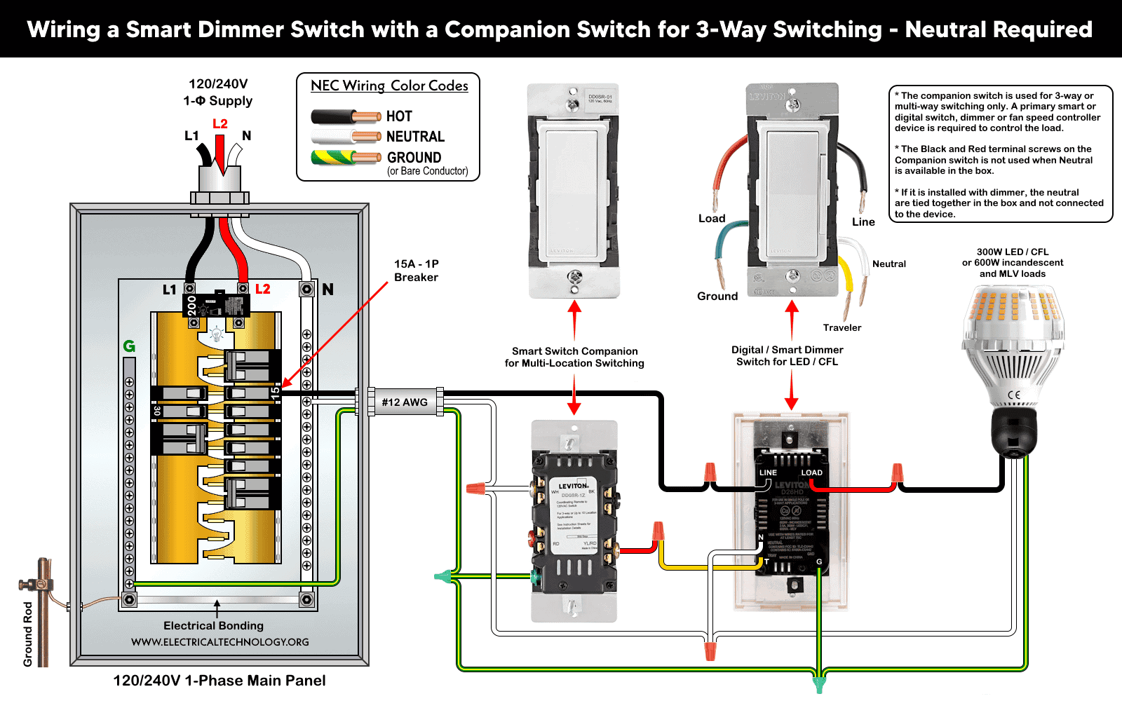
3-Way Wiring when Neutral Available in Both Switch Boxes
3-way circuit with neutral in both boxes using smart dimmer companion switch (DD00R-DLZ) with a smart dimmer switch (DDL06/DW6HD/DH6HD/D26HD) or smart switches (D315S / D215S) with smart companion switches (DD0SR-1Z or DD0SR-DLZ).
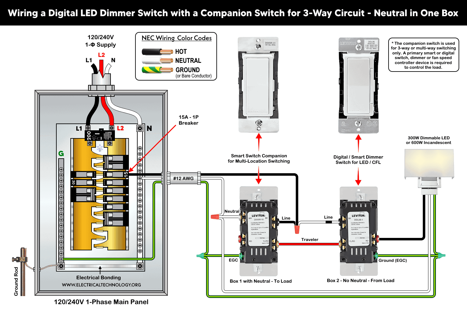
3-Way Wiring when Neutral Available in Only One Box
3-way circuit with neutral in one box using smart dimmer (DDL06) with a smart companion switch (DD0SR).
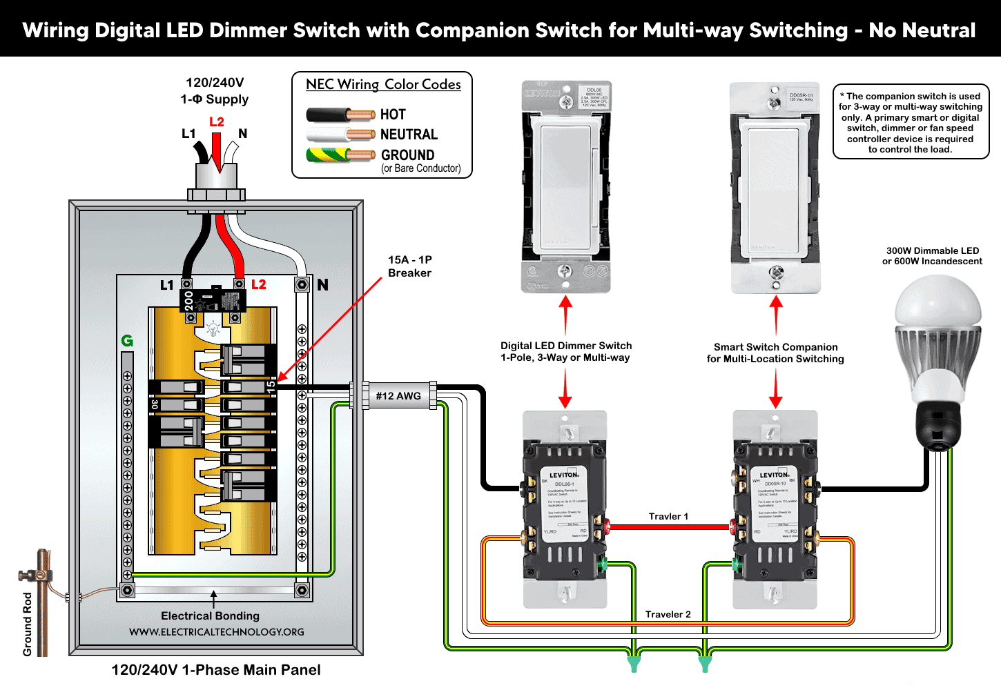
3-Way Wiring without Neutral Wire
3-way circuit without neutral connection using smart dimmer (DDL06) with a smart companion switch (DD0SR).
Instructions & Precautions.
- Make sure to disconnect the power supply by switching OFF the breaker in the main panel before doing any electrical work.
- Per NEC Table – 310.16 , 210.24.(1) and 240.4(D)(4), the correct breaker and wire size for a 15-Amp, 120V circuit is #14 AWG copper. Hence, use #14 AWG copper / copper-clade conductors with 15A smart switches.
- Other than built-in wires, strip 3/4″ (19 mm or 1.9 cm) for side wiring and 1/2″ (12.7 mm or 1.27 cm) for back wiring) insulation and tighten all terminal screws 14-18 in·lbs (1.6-2 N·m) of torque or as per given termination ranges.
- The wire length from smart dimmer/switch to other smart companion device should not exceed 300 ft (90 meters).
- 15A/120V switches and outlets/receptacles should be installed on 15A breaker only.
- Smart devices are for indoor use only.
- If you are unsure, contact a licensed electrician to do it according to the local area codes.
- The author will not be liable for any losses, injuries, or damages from the display or use of this information or if you try any circuit in wrong format. So please! Be careful because it’s all about electricity and electricity is too dangerous.
Resources:
Smart Devices Wiring Series
- How to Wire a Smart Switch in a 120/240V Load Center
- How to Wire 120/240V Smart Load Center with Smart Breakers
- How to Wire a Smart Breaker in a Smart 120/240V Panel
- How to Wire a Smart GFCI Breaker in a 120/240V Smart Panel
- How to Wire Smart AFCI/GFCI Breaker in a Smart Load Center
- How to Wire a 15A Wi-Fi Smart Outlet in a Smart Panel
- How to Wire 15A and 20A Wi-Fi Smart GFCI Outlets
- How to Wire Z-Wave Smart Switch, Dimmer & Fan Speed Controller
- How to Wire a Digital and Wi-Fi Smart LED Dimmer Switch
- How to Wire a Smart Switch Companion with a Smart Switch
- How to Wire a Smart Wireless Switch and Anywhere Companion
- How to Install a Wire-Free Smart Dimmer Anywhere Companion
Wiring Standard GFCI & Breakers
- How to Wire a 1-Pole Breaker
- How to Wire a 2-Pole Breaker
- How to Wire a 3-Pole Breaker
- How to Wire a 1-Pole GFCI
- How to Wire a 2-Pole GFCI
- How to Wire a 3-Phase, 3-Pole GFCI
- How to Wire a Tandem Breaker
- How to Wire GFCI Circuit Breakers
- How to Wire an AFCI Breaker
Wiring General Outlets & GFCI/AFCI Receptacles
- How to Wire an Outlet Receptacle? Socket Outlet Wiring Diagrams
- How to wire a GFCI Outlet?
- How to Wire an AFCI Outlet?
- How to a Wire 3-Way Combination Switch and Grounded Outlet?
- How to Wire a 15A – 125V Outlet – NEMA 5-15 Receptacle
- How to Wire a 20A – 125V Outlet – NEMA 5-20 Receptacle
- How to Wire a 15A – 250V Outlet – NEMA 6-15 Receptacle
- How to Wire a 20A – 250V Outlet – NEMA 6-20 Receptacle
- How to Wire a 50A – 125/250V Outlet – NEMA 14-50 Receptacle
Switches Wiring
- How to Wire Single Pole, Single Throw (SPST) as 2-Way Switch?
- How to Wire Single Pole, Double Throw (SPDT) as 3-Way Switch?
- How to Wire Double Pole, Single Throw Switch? Wiring DPST
- How to Wire Double Pole, Double Throw Switch? Wiring DPDT
- How to Wire Double Switch? 2-Gang, 1-Way Switch – IEC & NEC
- How to Wire 4-Way Switch (NEC) or Intermediate Switch as 3-Way (IEC)?
- How to Wire Auto & Manual Changeover & Transfer Switch – (1 & 3 Phase)
Sizing Breakers, Wires, and Panels
- How to Size a Load Center, Panelboards and Distribution Board?
- How to Determine the Right Size Capacity of a Subpanel?
- How to Find the Right Wire Size for 100A Service 120V/240V Panel?
- How to Size a Circuit Breaker?
- How to Find the Proper Size of Wire & Cable In Metric & Imperial Systems
- How to Size a Breaker and Wires in AWG with EGC for Load?
- How to Size Service-Entrance Conductors and Feeder Cables?
- How to Size Feeder Conductors with Overcurrent Protection
- How to Size a Branch Circuit Conductors with Protection?
- How to Size Equipment Grounding Conductor (EGC)?
- How to Size Grounding Electrode Conductor (GEC)?
- How to Size Main Bonding Jumper (MBJ)?
- How to Size Motors FLC, HP, Voltage, Breaker Size and Wire Size
- What is the Correct Wire Size for 100A Breaker and Load?
- What is the Right Wire Size for 15A Breaker and Outlet?
- What is the Suitable Wire Size for 20A Breaker and Outlet?
Finding the Number of Breakers/Outlets in a Circuit
- How to Determine the Number of Circuit Breakers in a Panelboard?
- How to Find the Number of Outlets on a Single Circuit Breaker?
- How to Find Voltage & Ampere Rating of Switch, Plug, Outlet & Receptacle
- How to Calculate the Number of Fluorescent Lamps in a Final Sub Circuit?
- How to Calculate the Number of Incandescent Lamps in a Final Sub Circuit?
- How to Determine the Number of Lighting Branch Circuits?
- How to Determine the Number of Branch Circuits? – 3 Ways
- How to Find the Number of Lights on a Single Circuit Breaker?
-
 How to Wire AC Level 2 EV Smart Breaker Charger – 40A/32A
-
 How to Wire a Countdown Timer Switch – 15 Mins to 12Hrs
-
 How to Wire a Digital & Smart Fan Speed Controller Switch
-
 How to Wire Humidity Sensor and Fan Control Switch
-
 Wiring Combo Humidity Sensor & Fan Control with Light Switch
-
 How to Wire a Smart Motion Sensing Dimmer Switch