How to Wire Double Switch? 2-Gang, 1-Way Switch – IEC & NEC
Installation of Combination Double Switch (NEC) AKA 2-Gang, 1-Way Switch (IEC) for 120/240V & 230V AC
What is Combination Double Switch (AKA 2-Gang, 1-Way Switch)?
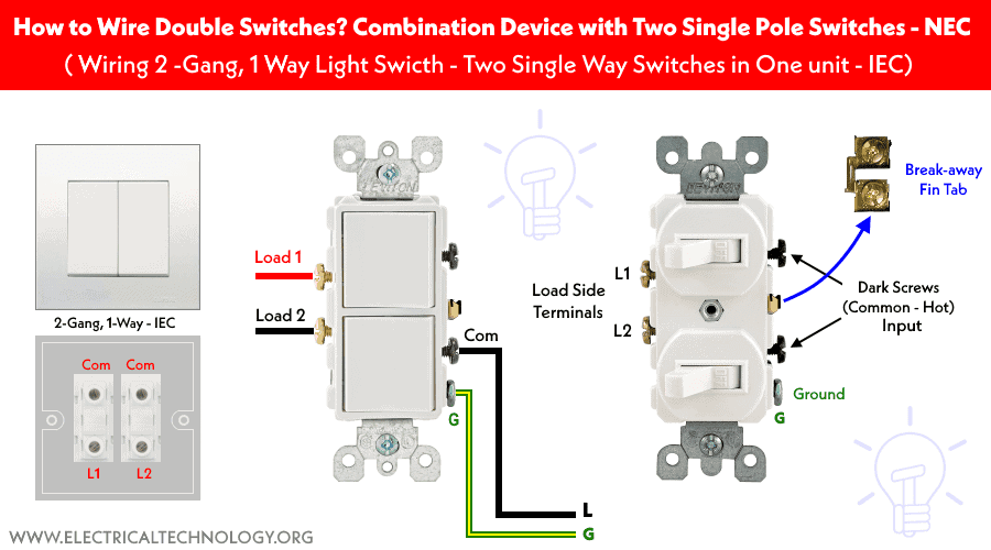
Double Switch (NEC) or 2-Gang, 1-Way Switch (IEC) represent the same thing i.e. it is a two single pole (SPST) switches in a single unit as a dual rocker switch. It is used as double rocker or double pole switches to control the residential small load appliances such as light bulbs and fans etc.
Good to know: Double switch is known as Double Rocker. Duplex Toggle, or Dual Rocker, Combination device of 2 single pole switches, Combo Double Toggle Switch or Combination Double Switch in North America (US – NEC). While it is known as Two Gang, One-Way switch (combination of two single-way switches) in the Europe, UK and IEC following countries. The “Gang” just represents the number of switches on the plate which is also known as “Throw”, “Rocker” or “Dimmer” while the “Way” describes the number of controlling circuits per switch e.g. one-way, two-way, three-way, four way etc. For example. a 1-Gang, 1-Way switch only control a single circuit (such as lighting) for ON and OFF operation.
Related Wiring Diagrams:
- How to Wire Single Pole, Single Throw (SPST) Switch? IEC & NEC
- How to Wire Single Pole, Double Throw (SPDT) Switch? IEC & NEC
Construction of Combination Device (Double Switch or 2-Gang, 1-Way)
The following figures represent the basic construction of double switch (NEC) and two gang, one way switch (IEC).
Click image to enlarge
The following diagram shows the the working operations of a Double switches (Combination of two switches in a single unit).
Click image to enlarge
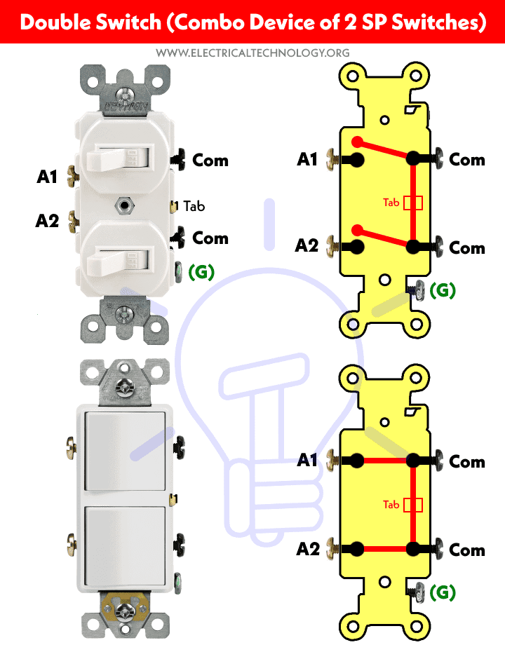
The following figures show the different views of Double Switch Combo Device.
Click image to enlarge

Let’s see how to wire them one by one for different load circuits according to NEC & IEC.
Wiring Double Switches for 120V/240V Circuits – NEC
How to Wire a Double Switch to a Ceiling Fan with a Light Bulb in One Unit?
The following wiring diagram shows how to control both light and fan using a combination double switch. It clearly shows that the Hot (Line) wire is connected to common screws that are bonded together via break-off fin. There are four wires connected to the terminal box of the ceiling fan with a light bulb.
Click image to enlarge
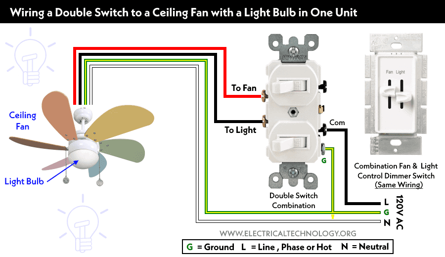
The Red wire as Hot connected to the ceiling fan and the Black wire as hot connected to the light bulb from the double switch load terminals. Finally, the Ground and Neutral wire is connected to the (common for both appliances) terminals in the ceiling fan box. This way, the upper switch controls the fan and the lower switch controls the light bulb in it for ON and OFF operations..
Keep in mind that you may use the combination fan and light control dimmer switch for the same purpose as it has the same wiring connections.
Related Posts:
Wiring Combination Device with Duplex Single Pole Switches to a Ceiling Fan & a Light Bulb?
The following diagram shows the controlling of an ordinary fan and a separate light bulb using a double switch (combination). It has the same wiring connection as above. The incoming hot wire is connected to the common screw of the double switch. The load terminals connected to the ceiling fan and light bulb. Also, both Neutral and Ground wire are connected to the fan and light.
Click image to enlarge
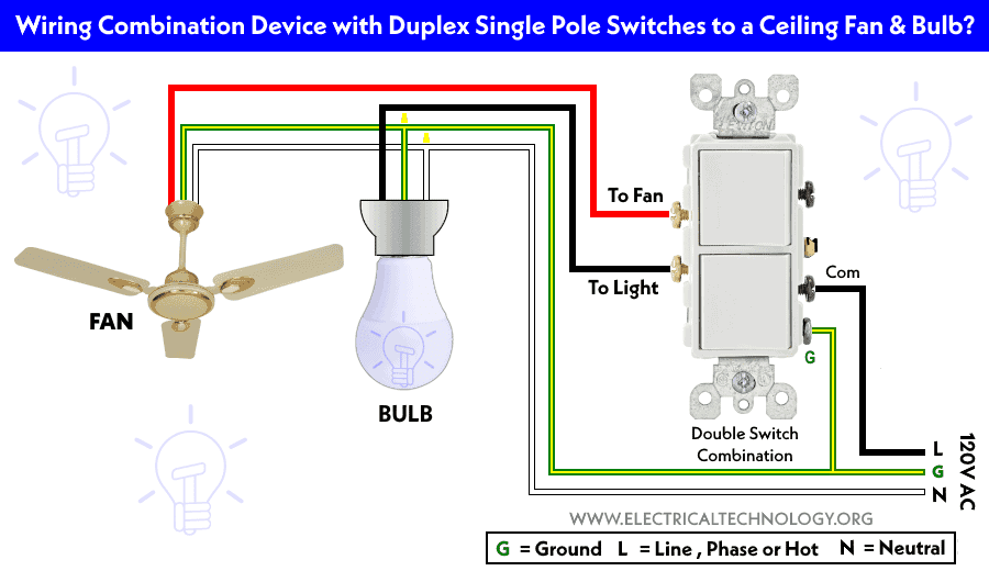
In this case, the upper switch (Red wire from the switch to the Fan) controls the ceiling fan and the lower switch (Black wire from switch to the light) controls the light bulb.
Wiring a Ceiling Fan & Light using Double Combination Dimmer Switch
This is the recommended way to wire a fan and light using a dimmer double switch combination to control the fan speed as well as light density.
As shown, the line (hot) is connected to the common screw of the dimmer switch. The load terminals of the double dimmer switch are connected to the fan and light bulb. Finally, both Neutral and Ground wires are connected to both load points.
Click image to enlarge
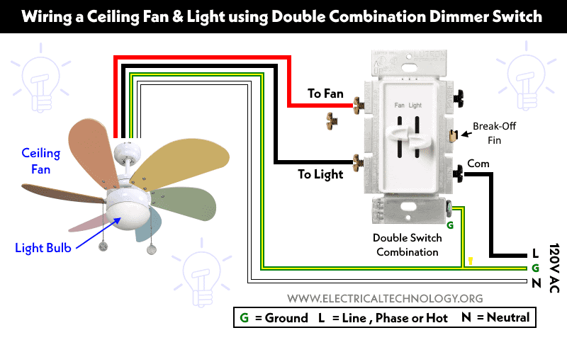
As shown, the upper switch is used to control the fan speed while the lower switch is used to control the light density as well as both ON and OFF operations.
Related Posts:
Wiring 2-Gang, 1-Way Light Switches for 230V Circuits – IEC
Controlling a Fan & Light Bulb in One Unit using a Two-Gang, One-Way Switch
The following wiring diagram shows how to control both ceiling fan and light bulb in it using a 2-Gang, 1-Way switch. As shown, the phase (line) wire is connected to both common screws. There are four wires connected to the terminal box of the ceiling fan with a light bulb.
Click image to enlarge
The Brown wire as phase from the L1 terminal of switch is connected to the ceiling fan and the Black wire as phase from the L2 terminal of switch is connected to the light bulb. Finally, the Neutral and Ground wire is connected to the common terminals in the ceiling fan box. This way, the first switch controls the fan and the second switch controls the light bulb in it for ON and OFF operations..
Keep in mind that you may use the combination fan and light control dimmer switch for the same purpose as it has the same wiring connections.
Related Posts:
- How to Wire Single Pole, Double Throw (SPDT) Switch? IEC & NEC
- How to Wire Double Pole, Double Throw (DPDT) Switch? IEC & NEC
- How to Wire 4-Way Switch (NEC) & Intermediate Switch as 3-Way (IEC)?
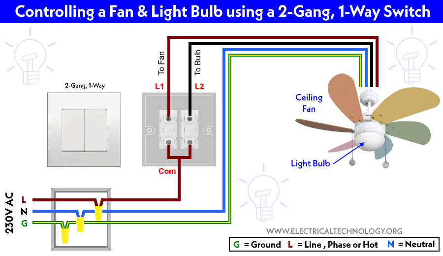
Wiring a Ceiling Fan & Bulb using a 2-Gang, 1-Way Switch
The following wiring diagram shows the controlling of a typical fan and a separate bulb using Two-Gang, One-Way switch. It has the same wiring connection as shown above. The incoming phase wire is connected to the common terminal of the 2-gang switch. The load terminals (L1 and L2) connected to the ceiling fan and light bulb respectively. Also, both Neutral and Ground wire are connected to both the fan and light bulb.
Click image to enlarge
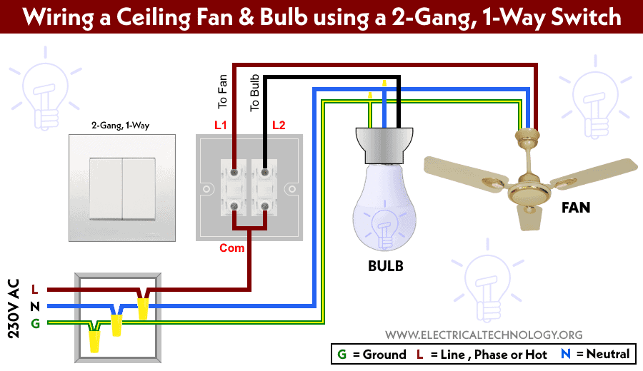
In this case, the Right side switch (brown wire from L1 terminal of switch to the Fan) controls ON and OFF operations of the ceiling fan and the Left side switch (Black wire from L2 terminal of switch to the light) controls the ON/OFF operations of the light bulb.
Related Posts:
- How to Control a Lamp by a Single Way or One-Way Switch?
- How to control each lamp by separately switch in parallel lighting circuit?
Precautions:
Related Posts:
- How to Wire an Outlet Receptacle? Socket Outlet Wiring Diagrams
- How to Find the Number of Outlets on a Single Circuit Breaker?
- How to Find Voltage & Ampere Rating of Switch, Plug, Outlet & Receptacle
- How to Wire a Pilot Light Switch? Wiring of 2 & 3 Way Neon Light Switches
- How to Wire Combo Switch and Outlet? – Switch/Outlet Combo Wiring Diagrams
- How to Wire an AFCI Combo Switch – AFCI Switch Wiring Diagrams
- How to Wire GFCI Combo Switch and Outlet – GFCI Switch/Outlet Wiring Diagrams
- How to Control Water Heater using Switches?
- How to Wire a Ceiling Fan? Dimmer Switch and Remote Control Wiring
- How to Wire Auto & Manual Changeover & Transfer Switch – (1 & 3 Phase)
- Automatic Bathroom Light Switch Circuit Diagram and Operation
- Staircase Wiring Circuit Diagram – How to Control a Lamp from 2 Places by 2-Way Switches?
- 2 Way Switch – How to Control One Lamp From Two or Three Places?
- How to Control One Light Bulb from Six Different Places using 2-Way & Intermediate Switches?
- Corridor Wiring Circuit Diagram – Hallway Wiring using 2-Way Switches
- Hospital Wiring Circuit for Light Control using Switches
- Tunnel Wiring Circuit Diagram for Light Control using Switches
- Godown Wiring Diagram -Tunnel Wiring Circuit and Working
- Hostel Wiring Circuit Diagram and Working
- How to Wire a UK 3-Pin Plug? Wiring a BS1363 Plug
- How to Wire a UK 3-Pin Socket Outlet? Wiring a BS1363 Socket
- How to Wire a Twin 3-Pin Socket Outlet? Wiring 2-Gang Socket
- How to Wire Combo Switch and Outlet? – Switch/Outlet Combo Wiring Diagrams
- Switch and Push Button Symbols
- Basic Electrical Wiring Diagrams


