How to Wire Single Pole, Single Throw (SPST) as 2-Way Switch?
Installation of SPST – 2-Way Switch (NEC) AKA 1-Way Switch (IEC) for 120/240V & 230V AC – 2-Way & 1-Way Circuits
What is SPST Switch?
SPST (stands for Single Pole Single Throw) switch is the most commonly used switch to control the ON and OFF operations of household appliances such as lighting points and fans etc. It is used to control a single operation either ON or OFF in an electric circuit.
Good to know: SPST switch is known as single pole, single throw, Two Way switch, toggle switch or Light switch in North America (US – NEC). While it is known as One Way Switch, Single Way Switch or 1-Gang, 1-Way Switch (where Gang represent the number of throw or switches on the plate) in the Europe, UK and IEC following countries.
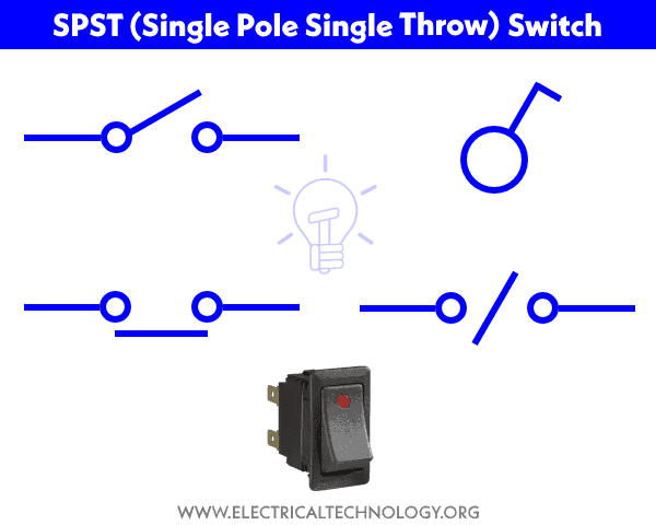
Symbol of SPST Switch
The following symbols represent the basic single pole single throw switches.
Construction of Single Pole, Single Throw Switch
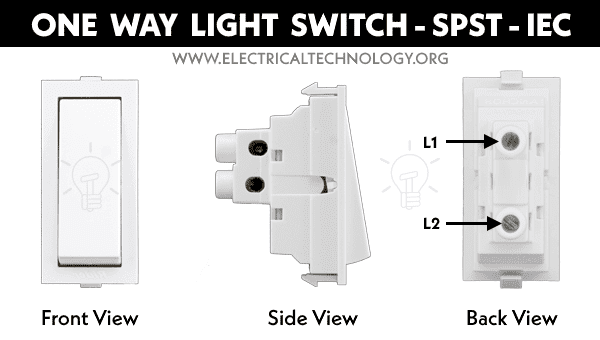
The Single Pole Single Throw switch has mainly two terminals for Hot IN and Hot OUT and an extra terminal as ground pin in North America. In the UK and IEC following counties, the single pole switch has only two terminals without ground pin.
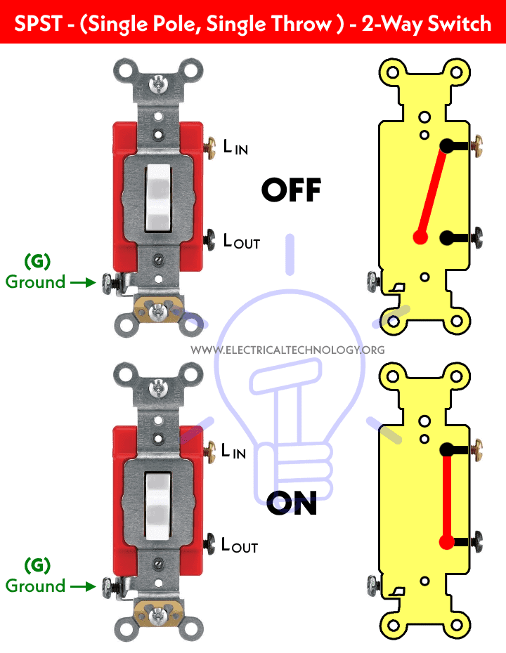
The following two figures show the main difference between US and UK single pole, single throw (SPST) switches.
Two-Way Switch – SPST, Single Pole, Single Throw – US – NEC

One Way Switch – SPST, Single Pole, Single Throw – UK – IEC
Let’s see how to wire them one by one for different appliances.
Click image to enlarge
Related Posts:
Wiring Single Pole, Single Throw Light Switches for 120V/240V Circuits – NEC
How to Wire a Single Pole, Single Throw Switch to a Light Bulb?
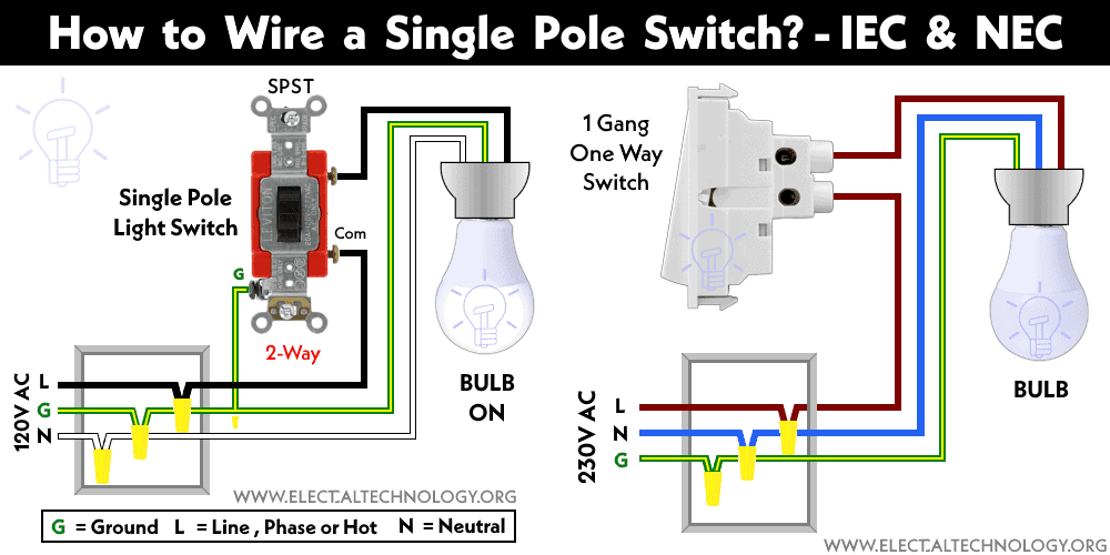
The following wiring diagram shows that how to wire and control a light bulb using an SPST switch. As shown in the fig below, there are three incoming wires from the breaker in the electrical box (junction box) viz, G (Ground), L (Line or Hot) and N (Neutral).
The ground wire is connected to the Ground terminal on the switch (Green with yellow stripe). The Line (as hot) is connected to the line terminal of the switch. Keep in mind that neutral wire is never connected to the switch.
Click image to enlarge
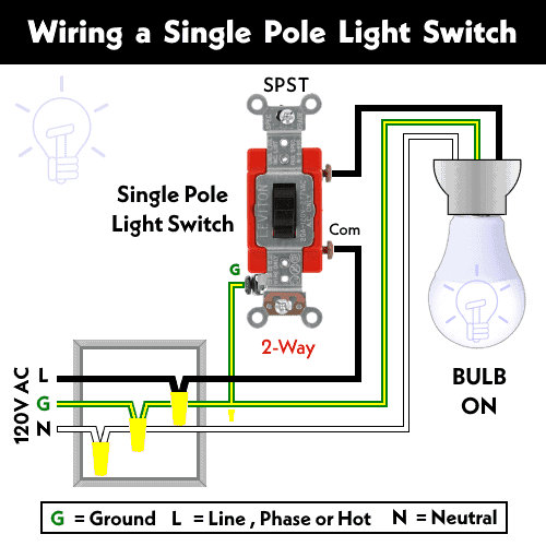
To control the light bulb using a single way switch, the ground wire (using wire nut in the electrical box) is connected to the bulb holder. Similarly, both Neutral and Hot wires are also connected to the LED light bulb. This way, the bulb is controlled via a single pole switch i.e. when the switch is ON, the light bulb will glow. If the switch is OFF, the light bulb will also OFF.
How to Wire a SPST Switch to an Outlet?
The SPST switch can be used for different appliances such as fans, standard outlets receptacles etc. The following fig shows how to wire a single pole, single throw switch to an outlet (for switched outlet) operation. In other words, the SPST switch is controlling the ON and OFF operation of the receptacle.
Click image to enlarge

Related Posts:
Wiring Single-Way (One-Way or 1-Gang, 1-Way) SPST Light Switches for 230V Circuits – IEC
A 1-Gang, single pole, single throw (also known as One-Gang, One-Way switch) followed by IEC (International Electrotechnical Commission) is totally different from SPST toggle & light switches by NEC (National Electrical Code) standards.
The one way switch has two terminals as shown in the above fig. The first terminal should be connected to the incoming phase wire and the second terminal should be connected to the load point e.g. lighting points etc.
How to Wire a One-Way (1-Gang, 1-Way) Switch to a Light Bulb?
In the following wiring diagram for 230V AC supply system – IEC, a 1-gang one way switch is used to control a CFL or LED light bulb. It clearly shows that the incoming Phase (Line) wire (brown Color) is connected directly to the first terminal of the switch. The second terminal of the switch is connected to the light bulb through brown color.
Click image to enlarge
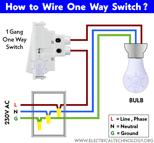
Similarly, the Neutral wire (blue or sky blue color) is directly connected to the light bulb from the junction box. Finally, the green wire is connected to the bulb holder.
Keep in mind that Green as Ground wire never connects to the light switch as compared to the NEC Codes.
How to Wire a One-Way Switch to a Socket?
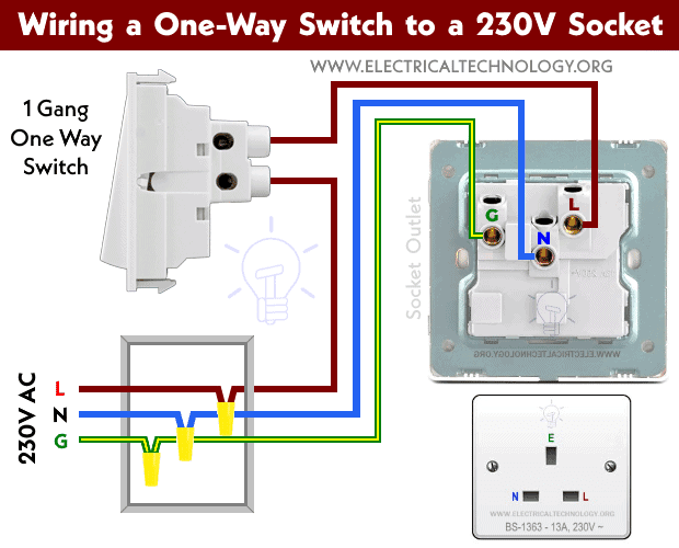
As mentioned above, the one-way switch can be used for different appliances such as light bulbs, fans, socket outlets etc. The following fig shows how to wire a one-way switch to 230V British socket (for switched socket) operation.
Click image to enlarge
Related Posts:
- How to Control a Lamp by a Single Way or One-Way Switch?
- How to control each lamp by separately switch in parallel lighting circuit?
Precautions:
Related Posts:
- How to Wire an Outlet Receptacle? Socket Outlet Wiring Diagrams
- How to Find the Number of Outlets on a Single Circuit Breaker?
- How to Find Voltage & Ampere Rating of Switch, Plug, Outlet & Receptacle
- How to Wire a Pilot Light Switch? Wiring of 2 & 3 Way Neon Light Switches
- How to Wire Combo Switch and Outlet? – Switch/Outlet Combo Wiring Diagrams
- How to Wire an AFCI Combo Switch – AFCI Switch Wiring Diagrams
- How to Wire GFCI Combo Switch and Outlet – GFCI Switch/Outlet Wiring Diagrams
- How to Control Water Heater using Switches?
- How to Wire a Ceiling Fan? Dimmer Switch and Remote Control Wiring
- How to Wire Auto & Manual Changeover & Transfer Switch – (1 & 3 Phase)
- Automatic Bathroom Light Switch Circuit Diagram and Operation
- Staircase Wiring Circuit Diagram – How to Control a Lamp from 2 Places by 2-Way Switches?
- 2 Way Switch – How to Control One Lamp From Two or Three Places?
- How to Control One Light Bulb from Six Different Places using 2-Way & Intermediate Switches?
- Corridor Wiring Circuit Diagram – Hallway Wiring using 2-Way Switches
- Hospital Wiring Circuit for Light Control using Switches
- Tunnel Wiring Circuit Diagram for Light Control using Switches
- Godown Wiring Diagram -Tunnel Wiring Circuit and Working
- Hostel Wiring Circuit Diagram and Working
- How to Wire a UK 3-Pin Plug? Wiring a BS1363 Plug
- How to Wire a UK 3-Pin Socket Outlet? Wiring a BS1363 Socket
- How to Wire a Twin 3-Pin Socket Outlet? Wiring 2-Gang Socket
- How to Wire Combo Switch and Outlet? – Switch/Outlet Combo Wiring Diagrams
- Switch and Push Button Symbols
- Basic Electrical Wiring Diagrams


