Thyristor & Silicon Controlled Rectifier (SCR) – Types & Operation
Thyristor and SCR (Silicon Controlled Rectifier) Construction, Operation, Types Characteristics & Applications
What is a Thyristor ?
The word “Thyristor” is a Greek word which means “Door” which is derived from the combination of two words i.e. Thyratron (a thyratron is a gas filled tube device used for control rectifier and high power electrical switching applications) and Transistor = Thyristor.
Thyristor is a four semiconductor layer or three PN junction device. It is also known as “SCR” (Silicon Control Rectifier).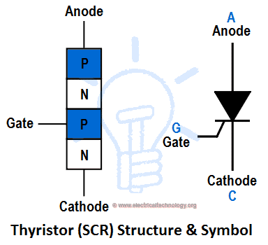
The term “Thyristor” is derived from the words of thyratron (a gas fluid tube which works as SCR) and Transistor.
Thyristors are also known as PN PN Devices. These devices are available in different shapes and types i.e. Uni-Junction Transistor (UJT), Silicon Controlled Rectifier (SCR), Triode for Alternating Current (TRIAC), DIAC (diode for alternating current), Silicon Control Switch (SCS) etc.
SCR and Thyristors are also known as Latching Devices. A latch is a type of switch, when it is closed once, it will remain in close position until someone opens the switch. In other words, when a switch is ON, it will be remained ON after removing the control signal is called latch.
Semiconductor devices having four layers with a control mechanism is termed as a thyristor. The term thyristor is mostly applied to silicon controlled rectifiers (SCR). The term is derived from Thyratron and transistor because such a device combines the rectification of thyratron and control action of transistors.
Thyristors have the ability to be controlled, fast response, it’s highly reliable because it can handle large current and needs a little maintenance. The cost of thyristor production is low and it is very efficient. Thyristors are used in controlling DC/AC motors. It is also used in improving power factor and as a switching device as well as in HVDC (High Voltage DC) transmission lines.
Thyristors have reduced the cost of development of drive systems by changing emphasis from dc motors to ac. It has replaced electromagnetic control systems. It is capable of handling power as high as 4MW(2,500A at 1600V).
- Related Post: Types of Rectifiers & Their Operation
Construction of a Thyristor (SCR)
It is obvious that SCR is a rectifier (PN) and a junction transistor (N-P-N) joined together to form a PNPN device. All the three terminals are taken from the outer P-type materials known as the anode, second from the outer n-type material known as the cathode and the third from the base known as the gate.
As earlier stated, silicon material is used for the production of SCR because of its ability to withstand high temperature, high thermal conductivity and less leakage of current in the p-n junction. The junctions are either diffused or alloyed. The material used for some p diffusion is aluminum.
The material for n diffusion is phosphorus. Contact with the anode is made with aluminum foil through the cathode and the gate by a metallic sheet. The PNPN pellet is braced properly with a tungsten or molybdenum plate to give it great mechanical strength so it can handle large current. One of the plates is soldered very well to a copper or aluminum stud which is threaded for attachment to a heat sink, this conducts the internal losses to the surrounding medium. The voltage rating of the can be increased by doping the inner two layers and by increasing their thickness.
Basic Operations of a Thyristor (Working of SCR)
All thyristors have similar if not the same principle of operation. Since all types of thyristor have similar modes of operations, we will use silicon controlled rectifier (SCR) as a case study.
As earlier mentioned, thyristor (SCR) is a four-layer semiconductor. It has three junctions, and terminals known as PNP while the junctions as J1, J2, and J3. The p region is the anode. The n region is the cathode while the inner p is known as the gate. The anode to cathode connection is made in series to the load circuit.
The device remains in a voltage blocking state until both the anode and the gate terminals have enough positive voltage that can trigger it to turn it on else it remains off. If the device is on, to revert it to voltage blocking state (off), the gate signal must be eliminated and the anode current reduced to zero such that the current will flow only in one direction. Each layer of a thyristor is made up of charge carriers.
These carriers diffuse until a voltage is built up which opposes further diffusion of the charge carriers. Some carriers have sufficient energy to cross the barrier created by the opposing electric field at each junction.
Types of Thyristors
Thyristors are of many types. Below are few and most frequently encountered devices viz;
- Silicon controlled rectifier (SCR)
- Gate turn-off thyristor (GTO) and Integrated Gate commutated thyristor (IGCT)
- Mos-controlled thyristor (MCT)
- Static Induction thyristor (SITh)
- TRIAC : triode for alternating current – A bidirectional switching device that contains two thyristor structures with common gate contact.
- ETO : emitter turn-off thyristor
- DIAC: Bidirectional trigger device
- SIDAC: Bidirectional switching device. Etc.
Characteristics of Thyristors
Knowing that thyristors have no moving parts, they do not produce noisy sounds during operation. It has high switching speed (from a forward conduction state back to non conduction state i.e. forward-blocking state). It’s cost of maintenance is low, it’s size is small and it has little weight. A thyristor can be operated for a very long time without developing fault, it also has the ability to withstand high current.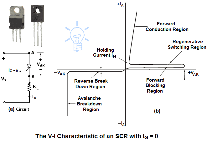
Silicon Controlled Rectifier (SCR)
As the term suggests, SCR is a controlled rectifier that is made from a silicon semiconductor material which has a third terminal mainly for voltage control purposes. Silicon was chosen for construction of SCR because of its ability to withstand high power as well as high temperature. The mode of operation of SCR differs from that of a diode because of the third terminal known as the gate designated by K.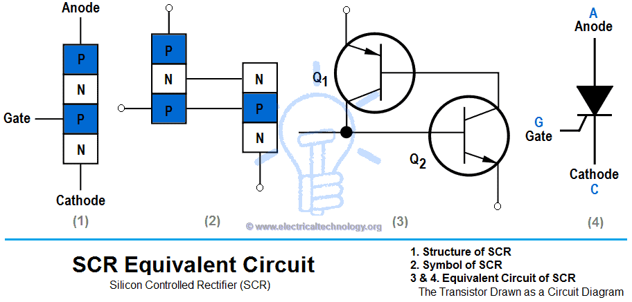
The gate determines when the circuit switches from open-circuit to short-circuit. The device is made of silicon because in silicon, the leakage of current is minimal compared to germanium.
Difference between Thyristors and Transistors
| S/No | Thyristors | Transistors |
| 1 | 4-Layers, 2 or more junctions devices | 3-Layers, 2 junction devices |
| 2 | Very fast response | Fast response |
| 3 | Very highly frequency | High frequency |
| 4 | Very highly reliable | Highly reliable |
| 5 | Very small Voltage Drop | Small Voltage Drop |
| 6 | Very long life | Long life |
| 7 | Very small to vary large power rating | Small to medium power ratings |
| 8 | Require only a small pulse for triggering and thereafter reaming in conducting stat | Require a continuous flow of current to remain in conducting stat |
| 9 | Very low power consumption | Low power consumption |
| 10 | High control capability | Low control capability |
| 11 | Very small Turn-ON and Turn-OFF time | Very small Turn-ON and Turn-OFF time |
- Related and detailed Post on: What is The Difference Between Transistor & Thyristor (SCR)?
Application & Uses of Thyristors and SCR
Below are the applications of SCR & thyristors;
- It is used as a Static Switch
- It controls the speed of DC and AC motors
- It can be used to convert AC into DC (Converters)
- It can also be used to inverts DC to AC (inverters)
- It is used in HVDC transmission lines
- It is used in relay control
- It is used in phase control
- It is used as a special power supply for electronics and aircraft
- It is used in improving power factor in transmission lines
- It can serve as a DC or AC breaker.
- Regulated Power Supply
- Battery Chargers
- Heater Controls
- Full wave bridge rectifier
- Fire Controls
- Full wave alternating current controls
- Emergency Lighting System
- Overvoltage Protection
- Motor Controls
- Ultrasonic Cleaning
- Induction heating control
- Mechanical Switches
- and High Power Industrial Control System such as Spot Welding and Seam Welding machines etc.
You may also read:
- Rectifier & Types of Rectifiers and their Operation
- NPN Transistor? Construction, Working & Applications
- PNP Transistor? Construction, Working & Applications
- Types of Inverters and their Applications
- 555 Timer. Working & Operation
- MAX232: Construction, Operation, Types and Application
- Types of ICs. Classification of Integrated Circuits and Their Limitation


cám ơn Công Nghệ Điện, trang này rất hay.
Tôi cần các mạch điều khiển scr điều khiển máy hàn điện ad và dc.
Nếu không có trở ngại gì thì xin giúp tôi.
Cám ơn nhiều.
Please describe in English… Thanks
I WANT ELECTRICAL DOMESTIC APPLIANCES CONSTRUCTION AND CIRCUIT DIAGTRAM
nice article
nice article
how to use thyristor to control motor speed ?