What is DIAC? Symbol, Construction, Working and Applications
DIAC – Construction, Operation, Advantages, Disadvantages & Applications
Semiconductor devices such as thyristors play vital role in power regulation in power electronics but since they conduct in only one direction, they not suitable for AC circuits. This is where DIAC and TRIAC comes into play. They regulate power supplied to AC loads such as controlling speed of motors.
- Related Post: TRIAC – Construction, Working and Applications

What is DIAC?
DIAC is an acronym that stands for “Diode for Alternating Current”. It is a two-terminal bidirectional switch that conducts in both directions when the applied voltage exceeds its break over voltage. It cannot amplify or offer controlled switching.
It belongs to the family of thyristors but It is an uncontrolled switch because it does not have a control or gate terminal. Its name implies that it is a diode that can conduct AC in both directions. It is mainly used for triggering other devices such as TRIAC due to its symmetrical switching characteristics.
Symbol of DIAC
The symbol of DIAC resembles two diodes in antiparallel ![]() . It has two terminals named A1 or MT1 and A2 or MT2. MT stands for main terminals. Since it can conduct in both directions, there are no anode and cathode terminal as shown in the figure.
. It has two terminals named A1 or MT1 and A2 or MT2. MT stands for main terminals. Since it can conduct in both directions, there are no anode and cathode terminal as shown in the figure.
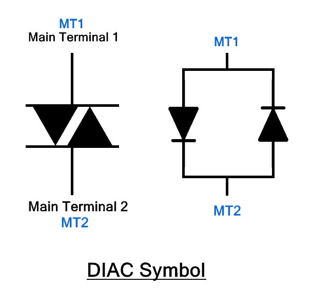
It does not have gate or controlling terminal. Instead, it turns on and off by increasing or decreasing the terminal voltage above or below its break over voltage.
Construction of DIAC
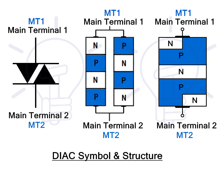
DIAC is a five layer device from the combination of two antiparallel SCR without the gate terminals. It has only two terminals MT1 and MT2. It has symmetrical structure from both terminals having equal width of the regions as well as its doping percentage.

DIAC can be constructed in 3-layer and 5-layer symmetrical structure. The 3-layer structure is mostly used which is made by either sandwiching N or P between its alternating layers forming PNP or NPN structure. The break over voltage of such DIAC lies around 30 volts.
The 5-layer DAIC construction resembles the combination of two SCR without the gate terminal. It has a symmetrical structure made of 2 P-layer and 3 N-layers. The terminal’s regions are made of both P and N layer. The doping and width of all layers are equal. The symmetrical structure provides symmetrical switching capabilities in both forward as well as reverse polarity.
- Related Post: What is the Difference Between DIAC and TRIAC?
Working of DIAC
The DIAC can conduct current in both directions unless the applied voltage falls below the break over voltage.
Suppose the applied voltage at MT1 is positive with respect to MT2, the junctions at the ends become forwards biased and the middle junction becomes reverse biased. At this moment, the applied Voltage V < VBO, so the middle junction remains reverse biased and does not allow current flow. The device remains in off-state.
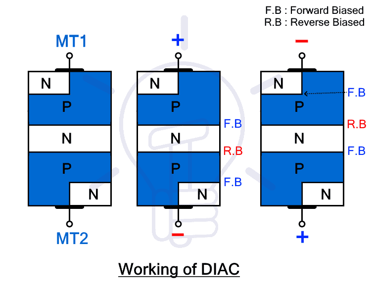
In order to trigger the DIAC into conduction, the applied voltage V must exceed break over voltage VBO. When it happens, avalanche break down occurs at the reverse bias junction and the current starts to flow through it. The DIAC is triggered into conduction and the voltage across it reduces to ON-state voltage drop.
Similarly, if the voltage polarities are swapped, the same process will repeat except the current will flow in reverse direction. There is no difference in operation whatsoever if the polarities are swapped. It has symmetrical switching characteristics for both voltage polarities i.e. its forward break over voltage is equal to reverse break over voltage.
The DIAC conducts current unless the current falls below the holding current limit. As soon as it falls below the said limit, the device switches into off-state.
V-I Characteristics of DIAC
The following characteristic curve shows the relation between the main voltage and main current of a DIAC. As you can see, the DIAC only operate in 1st and 3rd quadrant. It is a symmetrical device; therefore, the graph is symmetrical in both quadrants forming the shape of letter “Z”.

In 1st quadrant, the voltage and current are positive. As you can see, when the voltage is below the break over voltage VBO, the DIAC blocks the current except for the leakage current. The device remains in OFF-state. Once the voltage increases, the DIAC triggers into ON-state and the current rises. The voltage across the device starts to reduce to steady ON-state voltage.
The device operates similarly in the 3rd quadrant. The only difference between the 1st and 3rd quadrant is that the voltage and current are reverse. That is it.
Advantages & Disadvantages of DIAC
Advantages
Here are the advantages of DIAC:
- The DIAC offer symmetrical switching characteristics.
- Symmetrical switching helps in reducing the harmonics in a system.
- It has low on-state voltage drop.
- The voltage drop increases with the voltage
- It can be easily switches by increasing or decreasing the applied voltage.
- It offers smooth power control when used for triggering other thyristor and TRIAC
Disadvantages
- It is a low power device
- It only conducts when voltage increases above 30 volts.
- It cannot block high voltages.
Application of DIAC
The main application of DIAC is to trigger TRIAC. TRIAC has asymmetrical triggering due to difference in both halves of its structure. Due to this asymmetry, it does not trigger at the same voltage for forward and reverse current. The asymmetrical switching generates harmonics in the system. Greater the asymmetry, greater the harmonics. Harmonics causes numerous problems in a system and must be reduced.
The DIAC is connected in series to the gate of the TRAIC. Since the DIAC has equal forward and reverse break over voltage, it switches on when the voltage exceeds VBO in either direction. It triggers the TRIAC for both half of the AC cycle at equal voltage level offering symmetrical triggering.
It is a low power device and it is not suitable to regulate power on its own but with the combination of TRAIC, it can regulate high power circuit such as in motor speed control, heat control, dimmer etc.
Related Posts:
- What are Thyristor and SCR? Types, Working and Applications
- What is Rectifier? Types of Rectifiers and their Working Principle
- What is MOSFET? Working, Types, Operation, and Applications
- What is Diode? Construction & Working of PN Junction Diode
- What is BJT? Construction, Working, Types and Applications