Speed Control of DC Motor – Voltage, Rheostatic & Flux Control Methods
Speed Control Methods of DC Motor – Voltage, Rheostatic & Flux Control of Series & Shunt DC Motors
A DC motor is used to convert the direct current (DC) electrical power into mechanical power based on the forces produced by magnetic filed(s). The output of the motor is mechanical power in terms of rotation (speed) of the shaft.
According to the applications, we need to change the speed of the motor. So, deliberative change of speed is known as speed control of the motor.
The term speed control is different from the speed regulation. The speed regulation means that, to maintain a speed of shaft constant against the change in load.
EMF Equation of a DC Motor
the EMF equation of a DC motor is given below:
Eb = PΦNZ / 60A
Where;
- P = Number of poles
- Ф = Flux per pole
- N = Speed of motor (RPM)
- Z = Number of conductors
- A = Number of parallel paths
Once the motor is designed, the Number of poles (P), Number of conductors (Z), and Number of parallel paths (A) cannot change. So, these are fixed quantities.
Eb ∝ ΦN
Eb = kΦN
Where k = Proportionality constant
For DC motor, the EMF is also defined as;
Eb = V – IaRa
Where;
- V = Supply voltage
- Ia = Armature current
- Ra = Armature resistance
Now compare both equations;
kΦN = V – IaRa
k = N = V – IaRa / kΦ
From the above equation, the speed of the motor depends on supply voltage (V), Flux (Φ), and Armature resistance (Ra).
Therefore, the speed of a DC motor can be varied, changed and controlled by changing;
- Terminal voltage “V” (AKA Applied Voltage Control Method).
- External resistance with armature resistance Ra (AKA Rheostatic Control Method).
- Flux per pole Φ (AKA Flux Control Method).
Here, terminal voltage and armature resistance are associated with the armature circuit and flux per pole is associated with the field circuit.
So, the speed control methods of a DC motor are classified as;
- Armature Control Method
- Field Control Method
Now we discuss how to implement these methods for DC series, shunt, and compound motor.
Speed Control of DC Series Motor
Speed control of DC series motor is done by the armature control and field control methods.
Armature Resistance control method for DC series motor
In this method, a variable resistor or rheostat connected in series with armature resistor. The circuit diagram of this method is as shown in the below figure.
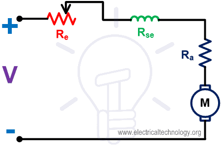
Fig-1
In series motor, armature winding is connected in series with the field winding. Therefore, armature current and field current are the same.
By varying the armature resistance, the armature current and voltage vary. If the value of external resistance increases, the voltage across the armature and current from the armature winding is reduced. And the speed will be decreased.
By this method, the speed of the motor only decreases from the level of speed when external resistance is not connected. The speed of a motor cannot increase from this level.
Here, the external resistance is connected in series with the armature. Therefore, the full load current will flow through the external resistor. So, it is designed to carry the full load current continuously.
The speed-current characteristic is as shown in the below figure.

Fig-2
Armature Voltage Control Method for DC Series Motor
In this method, the speed is controlled by varying the armature voltage (supply voltage). A separate variable voltage source is required in this method.
The speed of a motor is proportional to the supply voltage. So, if the voltage increases, the speed of the motor will increase and vice versa.
Generally, this method is not used. Because the cost of a variable power supply is very high. Hence, this method is rarely used for speed control.
Field Control Method for DC Series Motor
The field current is proportional to the flux. In this method, the speed is controlled by controlling the field current. There are two ways to control the field current;
- Field Diverter Control
- Tapped Filed Control
Filed Diverter Control
In this method, the series field winding is connected in parallel with diverter. The diverter is nothing but a variable resistor. Some parts of the field current will pass through the diverter.
From the equation of speed of a motor, the flux is inversely proportional to the speed of the motor. So, if the flux decreases, the speed will increase.
Lesser the value of diverter resistance less the field current and less the flux produced inside the motor. Hence, the speed of motor increases.
In this method, speed can be increased from the normal speed. The circuit diagram of this method is as shown in the below figure.
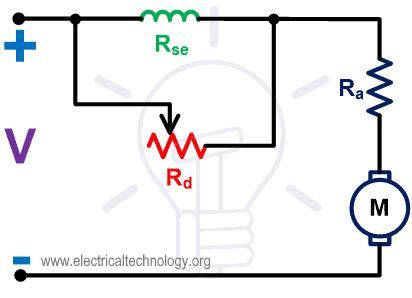
Fig-3
Tapped Field Control
There are tapping on the field winding to choose the number of turns in the winding. By choosing the tapping, the field current is controlled.
For a greater number of turns, the filed current is more and speed is less. For a lesser number of turns, the filed current is less and speed if more.
Therefore, in this method, the speed can be controlled by choosing proper tapping provided on the filed winding.
This method is used in electric traction for the speed control of the drive. The circuit diagram of this method is as shown in the below figure.
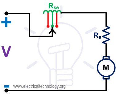
Fig-4
Speed Control of DC Shunt Motor
Methods of speed control for DC Shunt motor is similar to the DC series motor. Armature control and field control methods also applicable to the DC shunt motor.
- Related Post: Cable Size Calculation for LT & HT Motors
Armature Resistance Control Method for DC Shunt Motor
In this method, external resistance is added to the armature circuit. The field winding is directly connected with the supply. Hence, the field current will remain as same. And also, the flux will remain the same if the external resistance varies.
From the equation of speed, the armature current is proportional to the speed of the motor. If the value of external resistance increases, the armature current is decreased. Hence, the speed is decreased.
This method is used to control the speed below its normal value. The speed cannot increase more than the normal speed. The connection diagram of this method is as shown in the below figure.
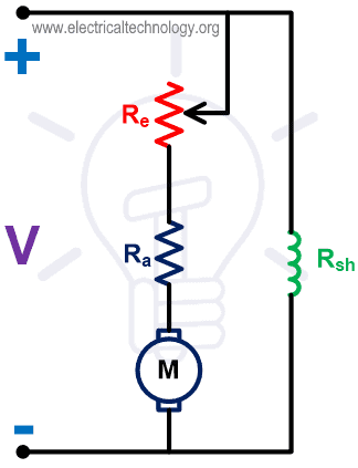
Fig-5
The speed-current characteristic is as shown in the below figure.
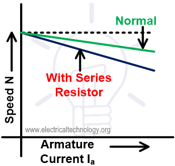
Fig-6
Field Control Method for DC Shunt Motor
In a DC shunt motor, the variable resistor is connected in series with the shunt field winding. The field current can be varied by this variable resistor. This variable resistor is also known as Field Regulator.
The connection diagram of this method is as shown in the below figure.
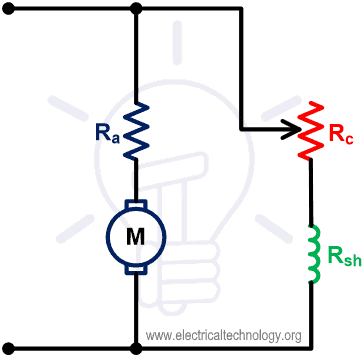
Fig-7
From the above circuit diagram, the equation of the shunt field current is;
By increasing the value of resistance, the field current decrease and hence the flux is reduced. From the equation of speed, the flux is inversely proportional to the speed. So, the speed increases as the flux decreased.
So, this method is applicable to control the speed above the normal speed. The speed cannot reduce below the normal speed in this method. The speed-current characteristic of this method is as shown in the below figure.
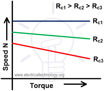
Fig-8
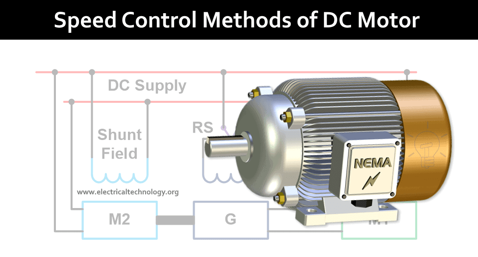
Armature Voltage Control Method for DC Shunt Motor
In this method, the field winding is supplied by the constant supply. But the armature winding is supplied by a separate variable DC source.
This method is also known as the Ward-Leonard method. The connection diagram of this method is as shown in the below figure.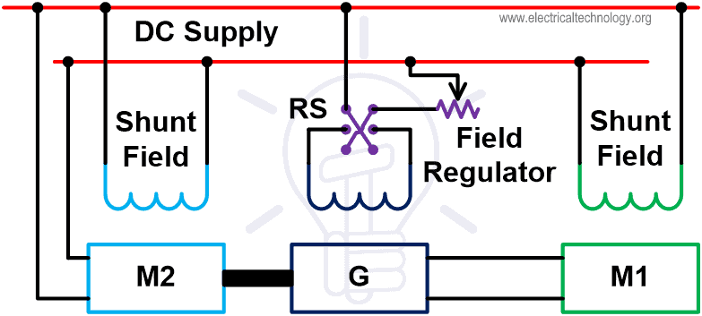
Fig-9
From the above diagram, we are controlling the speed of motor M1. This motor was powered by the generator G.
The shunt field winding is connected with the DC supply. The generator G is driven by the motor M2. The motor M2 is a constant speed motor and supplied from the DC supply.
The motor M1 starts rotating when the output voltage of generator G is fed to the motor. The speed of a motor can be controlled by controlling the output voltage of generator G.
The filed regulator is connected across the generator with a DC supply line to control the filed excitation.
By controlling the excitation voltage of the generator, the output voltage of the generator is controlled. And this voltage will control the speed of motor M1.
The switch RS is a Reverse Switch. This switch is used to toggle the terminal of field excitation. Because of this, the excitation current will reverse, and it will generate the opposite voltage.
So, this opposite voltage will reverse the speed of motor M1. Hence, by this method, the motor can run on both the direction. And speed can be controlled on both sides of the direction of rotation.
- Related Post: What is Motor Efficiency and How to improve it?
Advantages & Disadvantages if Ward Leonard Method
Advantages of Ward Leonard Method
The advantages of this method are summarized below;
- The speed of a motor can be controlled over a wide range.
- The operation of the motor is very smooth.
- The speed regulation of the motor is good.
- A motor can run with uniform acceleration.
- It has an inherent breaking capacity.
- Easy to reverse the direction of rotation and speed can be controlled in both directions.
Disadvantages of Ward Leonard Method
The disadvantages of this method are summarized below;
- It needs two additional machines (motor-generator set) with the same rating of the main motor. Therefore, the overall cost of this arrangement is very high.
- It produces more noise.
- Frequent maintenance required.
- This arrangement needs more space to install.
- Overall efficiency is low if the motor runs with light load conditions for a long period of time.
Application of Ward Leonard Method
This method is used where the motor to be controlled over a wide speed range. The application of the motor is very sensitive to speed, in this condition this method is very useful.
This method is used in the application like; cranes, excavator, elevator, mine hoists, paper machine, steel rolling mills, etc.
Related Posts:
- Direct Online Starter – DOL Starter Wiring Diagram for Motors
- Types of Motor Starters and Motor Starting Methods
- Why Motor rated in kW instead of kVA?
- Voltage And Power Equations of a DC Motor
- Electric Motors Symbols
- Star Delta Starter for Motor with Timer
- Star Delta Starter for Motor without Timer
- AC Drive – Working and Types of Electrical Drives & VFD
- DC Drive – Working and Types of DC Drives


Thank you for showing the speed control methods for DC Motors.
I would like to have your contacts as E -mail adress and whats’app No. Main is +254722811417 Name Abdiladir ali
You can subscribe to out mailing list and all new post will be delivered to your email address.