What is Power Electronics? Power vs Linear Electronics and Applications
How Power Electronics is Different than the Linear Electronics – Power Electronics Applications
What is Power Electronics?
The field of power electronics can be well understood by dividing it into two subcategories; power engineering and electronics engineering. The field of power engineering mainly deals with the generation, transmission, distribution, and utilization of electrical energy at higher efficiency.
Whereas, electronics engineering mainly deals with the generation, transmission, and reception of signals and data at a very low power level ranging from milliwatts to a few watts. In power electronics, the principles of electronics are placed into action for applications that are rated at a high power level ranging from tens of watts to hundreds of watts rather than low power levels ranging from milli-watts to few watts.
It is a field where equipment and devices are working on the principles of electronics but at a higher power level. In power electronics, a considerable amount of electrical energy is processed as compared to the processing of signals and data in the case of electronics engineering.
The electrical energy is processed and controlled by supplying the voltage and current in a form that is suitable according to the load demand. In a short sentence, if some might ask you, power electronics is a field where principles of electronics are applied for the control and conversion of electrical energy at a higher power level.

Block Diagram of Power Electronics System
Figure 1 below shows the basic block diagram of the power electronics system. The power input to the power electronics circuit can be AC or DC. Mostly, the power input is from the utility single or three phases at a frequency of 50 or 60 Hz.
The output of this system may be variable or fixed DC/AC voltage, or it may be variable frequency and voltage. The processed output (current, voltage, and frequency) of this system depends upon the requirement of the load.
The output values of the power electronics circuit are measured and these feedback signals are compared with the reference signals (desired values) to generate the control signals for the power electronics circuit that will reduce the error between the reference signal and the actual output signals.

For example, if a DC motor is connected as a load then the output voltage must be controllable to control the speed of the motor, or in the case of a three-phase induction motor, the circuit should have adjustable frequency and voltage at the output. The power flowing through such a such may be reversed and thus the roles of the input and the output will be interchanged.
The controller is a “Digital signal processors”, research and development in microelectronics have made it possible to develop such controllers. Further, the development in semiconductor technology has improved the power handling capability and switching operation of the modern power electronics systems.
Power Electronics VS Linear Electronics
In linear electronics, the semiconductor devices are operated in the active region and for isolation, an electrical transformer is used. It is due to operation in the active region that we have high power loss and less efficiency.
It becomes uneconomical as the high amount of energy is wasted and also it becomes difficult to remove the heat that is generated due to the dissipation of energy. The electrical transformer on the other hand is heavy which overall increases the size of the system.
As an example, consider the circuit in figure 2 which provides a regulated output voltage VO to the load. The input voltage from the utility is 240 V AC and the output at the load is around 5 V DC.
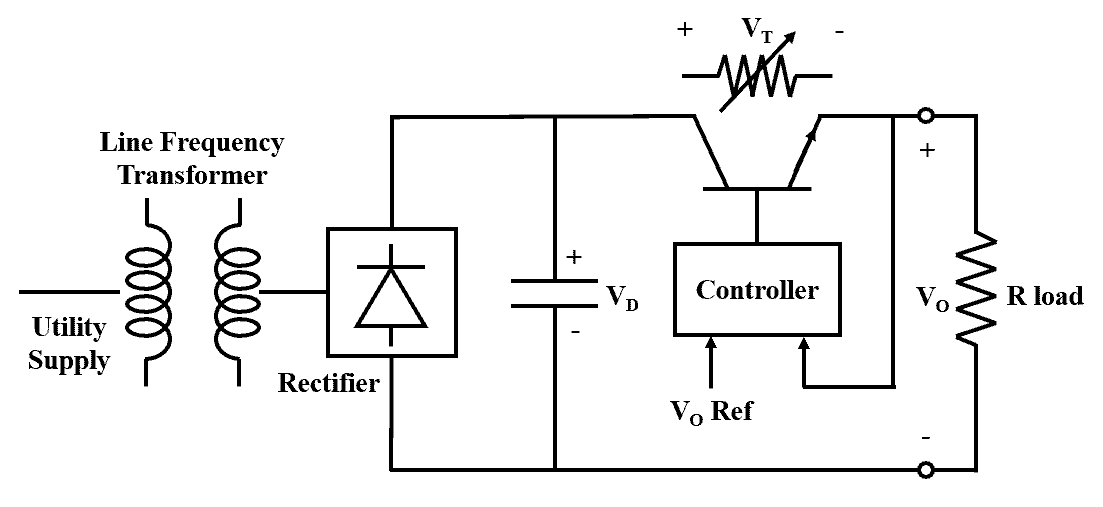
To provide isolation between the utility input and the output a line frequency transformer is used to provide electrical isolation and to step down the input line voltage to the required level. The AC to DC converter (i.e. the rectifier) converts the secondary low voltage winding AC output of the transformer into DC where further a capacitor is used to reduce the ripple content in the DC voltage VD.
This voltage waveform depends on the utility voltage magnitude which is usually around ± 10 % range of the nominal value of the utility voltage. It is important here to note that the line frequency transformer’s turns ratio is selected in such a way that the value of converted DC voltage VD is always greater than the regulated output voltage VO (i.e. VD > VO).
Now with this available input DC voltage VD which is connected in parallel across the resistive load and the transistor, the transistor is controlled in such a way that it creates a voltage drop VT across it to provide the resistive load with the desired regulated output voltage VO (VD = VT + VO). Thus, the transistor operates in the active region as a variable resistor which eventually results in power loss, generation of heat, and loss of efficiency of the entire system.
In the case of power, electronics take an example of the circuit shown in figure 3. In this circuit, without the utilization of a line frequency transformer the utility AC input is converted into DC voltage VD. Unlike linear electronics here the transistor operates in ON and OFF state at a very high frequency called switching frequency.
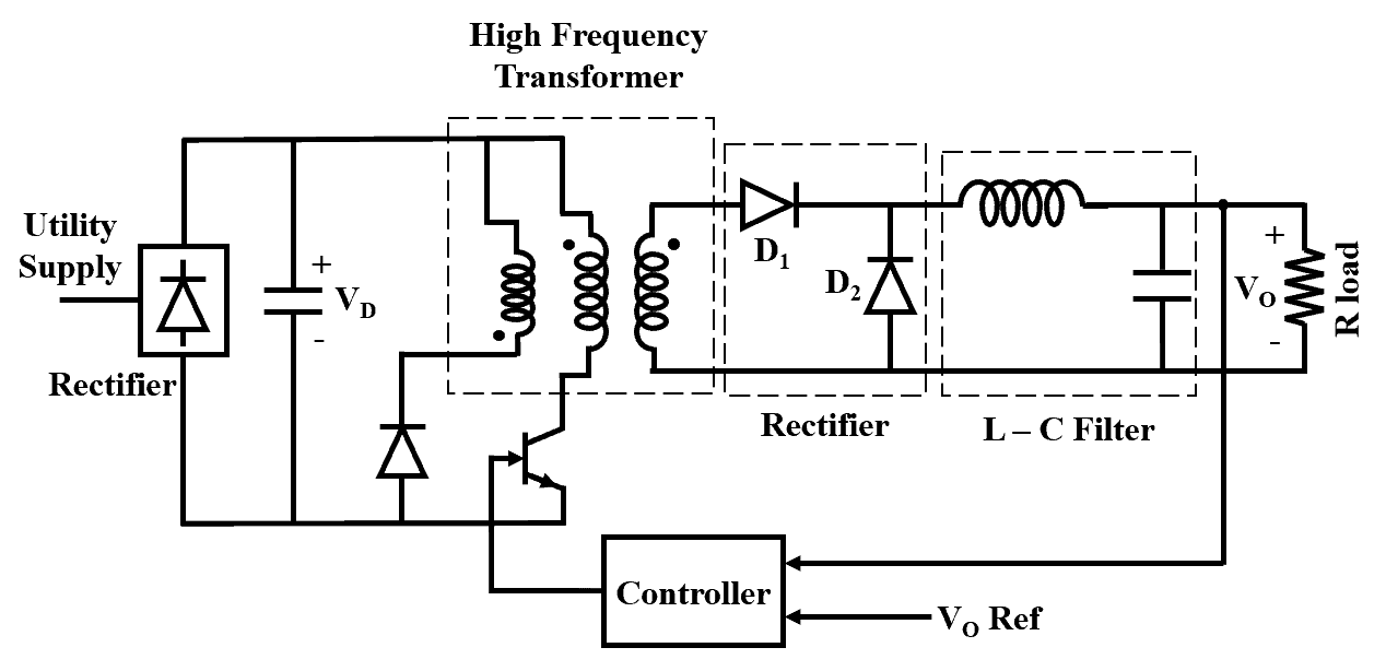
It is due to this high switching frequency in the circuit that the rectified DC voltage VD is converted in AC voltage (as the switch turns ON and OFF at high frequency the polarity of the voltage that appears across the windings alters). This helps in the use of a high-frequency transformer for the electrical isolation and voltage step down.
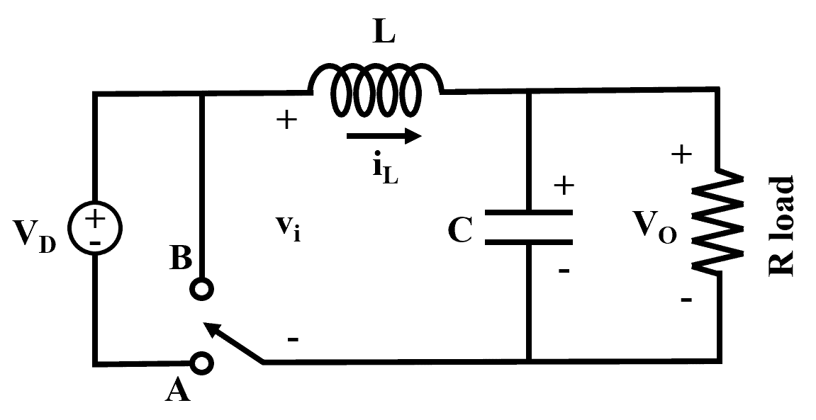
To simplify the understanding of the circuit shown in figure 3 let us simplify this circuit with an imaginary two-position switch as shown in figure 4. During the interval tON the switch is in position A and the transistor is ON and the diode D1 conducts whereas D2 acts as an open circuit. During the interval tOFF the switch is in position B and the transistor is OFF and the diode 2 conducts whereas D1 acts as an open circuit. As a result, the voltage vi in figure 4 has a voltage of VD and zero when the switch is positioned at A and B respectively.
vi = Vi + Vripple (t)
Where Vi is the DC average voltage of the vi as shown in figure 5 below and Vripple (t) is the instantaneous ripple voltage as shown in figure 6 has an average value of zero. The low pass filter formed by the L-C elements helps in reducing the ripple content in the output and allows only the desired average value of the input voltage that is,
Vo = Vi
Now from the waveforms in figure 5, it can be seen that the Vo is the average output voltage as,
![]()
![]()
If VD = 4 V, TS = 10 ms, and tON = 7 ms then the average output voltage is given as,
![]()


Now from the above equation 3, it is clear that the value of the output voltage can be changed by changing the ratio of ON time / Period of the cycle, and this ratio is called the duty cycle D of the switch. The ON time tON is varied and the frequency fS of the period TS is kept constant.
Thus, in power electronics due to the high-frequency switching operation of the transistor as compared to the only active region operation in linear electronics the power loss is minimized.
Certainly, there is a power loss when the switch operates at high frequency from ON to OFF state and vice versa. But it is proportional to the switching frequency which is far less than the losses that occur in the linear electronics system. With the higher frequency of operation, the weight and size of the transformers and the filter components in the system are minimized resulting in a compact assembly. But the cost of such high-frequency transformers and filters increases with the increase in switching frequency.
Now as we discussed before the that there is a power loss due to the switching operation and it is proportional to the switching frequency, the higher the switching frequency more is the power dissipation. So one must select a switching frequency such that it compromises between the power dissipation (i.e. efficiency) and the cost of the entire system.
Related Posts:
- Digital to Analog Converter (DAC) – Types, Working & Applications
- Analog to Digital Converter (ADC) – Block Diagram, Factors & Applications
Power Electronic Converters & Applications
Power electronic systems consist of one or more than one power electronic converter. The control and the characteristics of the semiconductor devices allow the converter to process the input to the required level at the output. The following are the classification of the power electronic converters along with their applications.
- Diode Rectifiers: Diode rectifier converts an AC input from an AC source or utility to a required level of fixed DC voltage. The input can be single-phase or three-phase and so is the rectifier designed accordingly to the input phase.
Applications: Electroplating, electrochemical processing, power supplies, electric traction, battery charging, and UPS, etc.
- AC to DC Converters: It converts a constant AC input voltage to a variable DC output voltage. These converters are also fed from a single-phase or three-phase supply. They are also known as naturally commuted or line commuted converter as the use the line voltage for their commutation.
Applications: Synchronous machines, metallurgy, DC drives, and chemical industries, etc.
- DC to DC Converters: It converts a constant DC input voltage to a variable DC output voltage. Depending on the type of application they are classified as buck, boost, and buck-boost.
Applications – DC drive, battery-driven vehicles, renewable energy systems, Switching mode power supplies, and UPS, etc.
- DC to AC Converters: It converts fixed DC voltage into variable AC output voltage, the output may be variable frequency and variable voltage.
Applications: Renewable energy systems, induction motor, synchronous motor, and UPS, etc.
- AC to AC Converters: It converts a fixed AC input voltage into variable AC input voltage. The output frequency may or may not be different than the input frequency.
Applications: Speed control of AC fan motors, lightning control, large AC drives, and pumps, etc.
Conclusion
In the above article, we studied the concept of power electronics i.e. it’s the combination of power and electronics engineering. We also saw its block diagram structure and how it is used for the process and control of power. We studied how power electronics is different than linear electronics systems in terms of efficiency, size, and power handling capability. And finally, we had a brief look into the classification of different types of power electronics circuits/converters along with their different areas of application. This article helped us understand the basic concept and the need for a power electronics system, which is a significant and emerging field in our modern electrical world.
Related Posts:
- Types of Inverters and their Applications
- Bipolar Junction Transistor (BJT) | Construction, Working, Types & Applications
- Thyristor & Silicon Controlled Rectifier (SCR) – Thyristors Applications
- What is PNP Transistor? Construction, Working & Applications
- What is NPN Transistor? BJT Construction, Working & Applications


Thank you for the explanatory article on power electronics.