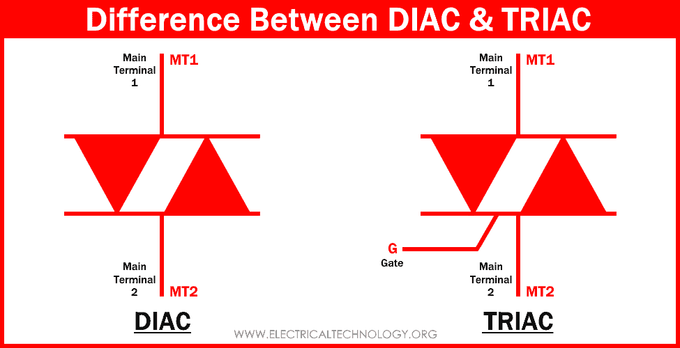
Difference Between DIAC and TRIAC
Main Differences Between DIAC & TRIAC
Regulating and controlling of the power supplied to a load is very important in order to reduce the wasting of energy and efficiently use of energy. Electrical and electronics play a major role in doing so through the use of semiconductor devices. DIAC and TRIAC are semiconductor devices used for regulation of such power supplied to the load.
These semiconductor devices are used to control the AC power supplied to load such as in controlling the speed of motors used in any application. Semiconductor devices such as SCR, DIAC, TRIAC & other thyristor family components having compact & small size are used due to their fine power control & high efficiency.
In order to understand DIAC & TRIAC better, we have to study SCR since they are the modified version of SCR.
SCR
SCR or Silicon Controlled Rectifier is a semiconductor component that belongs to the thyristor family. It is a four-layer device made of alternating P & N-layers PNPN. There are 3 PN junctions. It is a unidirectional controlled switch used for rectification and regulation of alternating current.
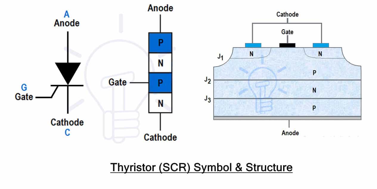 It has 3 terminals: Anode (A), Cathode (C) & Gate (G). The anode & cathode are the main terminals used for the conduction of current while the Gate terminal is the control terminal used for triggering or firing the SCR.
The Anode lead is connected with the outermost P-layer while the Cathode lead is connected with the outermost N-layer. While the gate lead is connected with the middle P-layer.
SCR works in three modes: Forward Blocking, Forward Conduction & Reverse Blocking Mode. In forward blocking mode, the SCR is connected in forward bias without any triggering pulse at the gate. In this mode, the SCR does not conduct.
 In reverse blocking mode, the SCR is connected in reverse bias as shown in fig (c). The SCR does not conduct in this mode even if there is a gate signal.
In forward conduction mode, the SCR is connected in forward bias as shown in fig (b) & it is triggered by applying a triggering pulse at its gate terminal. Forward conduction also occurs if the voltage exceeds its breakdown voltage.
The operation of SCR is very simple. When the anode is connected to a higher voltage than the cathode, the two PN junctions at the ends become forward biased while the middle junction is in reverse bias. The reverse junction does not allow the flow of current. A positive voltage pulse at the gate triggers the SCR into conduction by switching the middle junction into forward bais.
When the SCR is in forward conduction mode, removing the gate pulse will not switch it off. But the voltage between anode & cathode must be brought down so that the current falls below the “holding current” limit.
A thyristor a unidirectional switch that only allows current in one direction. It can only allow a half-wave of alternating current. it cannot conduct current in the reverse direction. It is triggered by applying only a positive gate pulse.
SCR’s Key Points
- SCR stands for Silicon Controlled Rectifier
- It is a unidirectional controlled switch
- It has 4 alternating layers
- It has 3 PN Junctions
- It has 3 terminals Anode, Cathode & Gate
- It has 3 operation modes: Forward Blocking, Forward Conduction & Reverse Blocking.
- In Forward blocking mode, it does not conduct even it is in forward bias (anode voltage higher than cathode voltage)
- Applying only a positive voltage pulse to the gate triggers SCR in forward conduction mode.
- In reverse blocking mode, the cathode voltage is higher than the anode & the SCR does not conduct.
- It does not stop conduction upon removal of the gate pulse.
- In order to stop conduction, the current must be drawn below the holding current limit.
- It is a latching device, considering the current flowing does not reduce below the latching current limit.
DIAC
A DIAC is an acronym that stands for “Diode for Alternating Current”. As the name suggests, it is a diode for conduction alternating current. It a bidirectional semiconductor uncontrolled switch capable of conducting current in both directions. It starts conduction when the applied voltage increases above the break-over voltage VBO. The main function of a DIAC is to help in activating TRIAC to perform symmetrical switching.
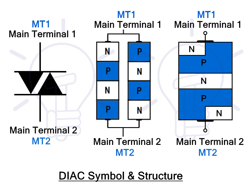 It is a two-terminal device made from a combination of two antiparallel SCRs without the gate terminals. The two terminals of DIAC are named Main Terminal 1 (MT1) & Main Terminal 2 (MT2). The DIAC is designed in such a way that it is symmetrical from both sides having equal regions.
DIAC is like a diode that switches ON when the applied voltage exceeds a certain limit except it can switch ON in both directions. It does not conduct when there in either direction when the voltage is below break over voltage VBO which is 30v in most cases. Once the voltage exceeds VBO, the DIAC switches ON & the voltage across DIAC falls down to 5 volts.
DIAC’s Key Points
- DIAC stands for Diode for Alternating Current.
- It is a bidirectional uncontrolled switch.
- It has 2 terminals.
- Its terminals are named main terminal 1 & main terminal 2.
- There is no control input.
- It switches ON for both directions of current flow.
- It switches ON when the applied voltage exceeds break-over voltage.
- It cannot block higher voltages in either direction.
- It only stops conduction when the voltage becomes very low far below break-over voltage or the current falls below the holding current limit.
- It has a symmetrical structure.
- It has symmetrical firing for both halves of the AC wave or the current flowing in both directions. thus no harmonics are produced.
- It has very low power ratings.
- It is mostly used for triggering TRIAC due to its symmetrical response.
Related Posts:
- PNP Transistor? Construction, Working & Applications
- NPN Transistor? Construction, Working & Applications
TRIAC
TRIAC stands for “Triode for Alternating Current”. It is a semiconductor controlled switch that can conduct in both directions. It is made from a combination of two SCR in an antiparallel configuration. TRIAC is used for regulating power in AC circuits & it can regulate both halves of the AC cycle.
 Since it is made by the combination of two antiparallel SCR, it has 4 layers & three terminals: Main terminal 1(MT1), Main terminal 2 (MT2) & gate. There is no Anode & cathode because it can conduct in both directions. The gate terminal is connected to both the P & N regions of each SCR.
The TRIAC can be triggered by a positive or negative gate pulse. But generally, the positive pulse is used for operation in the 1st quadrant & the negative pulse is used for operation in the 3rd quadrant. In the 1st quadrant, both the current and voltage across the TRIAC is positive while in the 3rd quadrant both are negative. These two quadrants imply the two halves of AC waves positive half & negative half. Although there is a slight difference in the firing due to the different gate regions (P & N region) in each half.
TRIAC’s Key Points
- TRIAC stands for Triode for Alternating Current.
- It is a bidirectional controlled switch.
- It has 3 terminals.
- Its terminals are named main terminal 1, main terminal 2 & Gate terminal.
- It is made from the combination of two SCRs in antiparallel.
- The gate is formed by the P-region of one & the N-region of other SCR.
- The gate is used for triggering TRAIC in both directions.
- It can be triggered by either a positive or negative gate pulse.
- It conducts even when there is no gate pulse.
- Only switched off by reducing the current below holding current limit.
- It does not conduct when there is no gate pulse in either direction.
- It has a slight non-symmetrical structure due to its gate regions.
- Due to non-symmetry, it has non-symmetrical firing.
- The non-symmetrical firing of TRIAC generates harmonics in the system.
- Its firing can be controlled form 0°-180° & 180°-360° of firing angle.
- To eliminate this non-symmetry, DIAC is used for triggering TRIAC.
- It can block very high voltages in both directions
Related Posts:
- Difference Between Microprocessor and Microcontroller
- Difference Between 8085 & 8086 Microprocessor – Comparison
Key Differences Between DIAC & TRIAC
| DIAC | TRIAC |
| DIAC is an acronym for “Diode for Alternating Current”. | TRIAC is an acronym for “Triode for alternating current”. |
| It is a diode for AC that allows current in both directions when the applied voltage increase above break overvoltage. | It is a bidirectional SCR that conducts in both directions when it is triggered using gate pulse. |
| DIAC has 4 alternating layers with equal regions. | it is made of 4 layers of alternating layers. |
| It has 2 terminals: Main terminal 1 (MT1) & main terminal 2 (MT2). | It has 3 terminals: Main terminal 1(MT1) & Main terminal 2 (MT2) & Gate. |
| It is an uncontrolled bidirectional switch. | It is a controlled bidirectional switch. |
| There is no firing angle. | TRIAC has a firing angle from 0° to 180° for the positive half & from 180° to 360° for the negative half. |
| It is made by the combination of two SCRs in antiparallel without any gate terminal. | It is made from a combination of two SCR with a common gate terminal. |
| It has a symmetrical structure i.e. same structure in both current directions. | TRIAC has a slight non-symmetrical structure due to different gate regions in both halves. |
| It does not have any control input or gate terminal. | It has a separate control input used for triggering the TRAIC. |
| It cannot block the voltages above 30 volts. | It can block very high voltage in the range of 600 to 1000 V. |
| It has very low power ratings. | It has a very high power rating in the range of 15KW. |
| It is triggered by increasing the voltage above break over voltage usually 30V. | It is triggered by applying an either positive or negative voltage pulse. |
| DIAC offers a very symmetrical response in triggering. | TRIACs triggering is not symmetrical & require DIAC to help it in firing symmetrically. |
| The DIAC has very low power ratings therefore it is mainly used for triggering TRIAC. | The TRIAC is used in supplying controlled power to AC loads, Speed control of fans & motors, dimmers in lamps & lights, etc. |
Related Posts:
- Difference Between CPU and GPU – Comparison
- Difference between Analog and Digital Circuit – Digital vs Analog
Properties & Characteristics of DIAC & TRIAC
The following different properties differentiate both DIAC and TRIAC having different characteristics and applications.
Structure
- DIAC is a 4 layer device made from alternating P-layer & N-layers.
- It has a symmetrical structure with equal regions.
- It is made from the antiparallel combination of two SCRs without the gate terminal.
- TRIAC has 4 alternating semiconductor layers.
- It is made from an antiparallel combination of two SCRs with a common gate terminal.
- The gate terminal is connected with the P-region of one SCR & the N-region of the other SCR.
- Therefore, the TRIAC’s one half is not perfectly symmetrical to the other.
Terminals
- DIAC has two terminals: Main Terminal 1 (MT1) & Main Terminal 2 (MT2).
- TRIAC has three Terminals: Main Terminal 1 (MT1), Main Terminal 2 (MT2) & Gate terminal.
Triggering
The triggering refers to the switching ON of a device into a conduction state.
- DIAC triggers into conduction state when the voltage between its terminal exceeds the break over voltage VBO.
- TRIAC is triggered into a conduction state by applying either a positive or negative voltage pulse at its gate terminal.
Characteristics Curve
The symmetry of the characteristic curve is very important for bidirectional current devices. A component having a symmetrical structure has a symmetrical characteristic curve
- DIAC has a symmetrical characteristic curve for both halve of the AC cycle due to its symmetrical structure.
- TRIAC has a slight non-symmetrical structure & due to this, it has non-symmetrical firing.
- The non-symmetrical firing generates harmonics in the system.
Control
- DIAC is an uncontrolled switch because there is no control input to triggered it on command.
- TRIAC is a controlled switch & its switching can be controlled using the gate terminal.
Power Ratings
- DIAC has very low power ratings.
- TRIAC has very high power ratings in the range of 15 KW.
Application
- The DIAC due to its very low power rating & symmetrical switching is used for triggering TRAIC in a circuit.
- TRIAC is used for controlling power fed to any AC circuit such as in speed control of fan, motor or dimming of lights.
Related Posts:
- Difference between Electron Current and Conventional Current
- Difference Between RAM and ROM – Comparison
- Difference Between Synchronous and Asynchronous Transmission
- Difference between Inverter & UPS – Uninterruptible Power Supply
- Difference Between Online UPS and Offline UPS – Which One is Better?
- Bipolar Junction Transistor (BJT) – Formulas and Equations
- Transistor, MOSFET and IGFET Symbols
- Thyristor, SCR, DIAC and TRIAC Symbols