What is TRIAC? Symbol, Construction, Working and Applications
TRIAC – Construction, Operation, Advantages, Disadvantages & Applications
Thyristors are widely used semiconductor-based devices for the regulation of power. However, they can conduct in only one direction just like a diode which makes them suitable for DC power regulation. Whereas, TRIAC which belongs to the family of the thyristor can conduct in both directions as well as offer full control over the power supplied. Therefore, they are used for AC power regulation.
- Related Post: DIAC – Construction, Working and Applications
What is TRIAC?
TRIAC is an acronym that stands for “Triode for Alternating Current”. Triode means a three-terminal device while AC means that it is used for switching Alternating current. It is a three-terminal bi-directional switch that conducts in both directions. It is made from the combination of two SCRs in anti-parallel with their gates joined together.
The three terminals are Gate, A1 or MT1 and A2 or MT2. It does not have an anode and cathode like a thyristor because it can conduct in both directions and it does not matter if the terminals are swapped.
TRIAC can be triggered into conduction by either positive or negative gate current in both directions. While it switches off when the main current falls below the holding current limit.
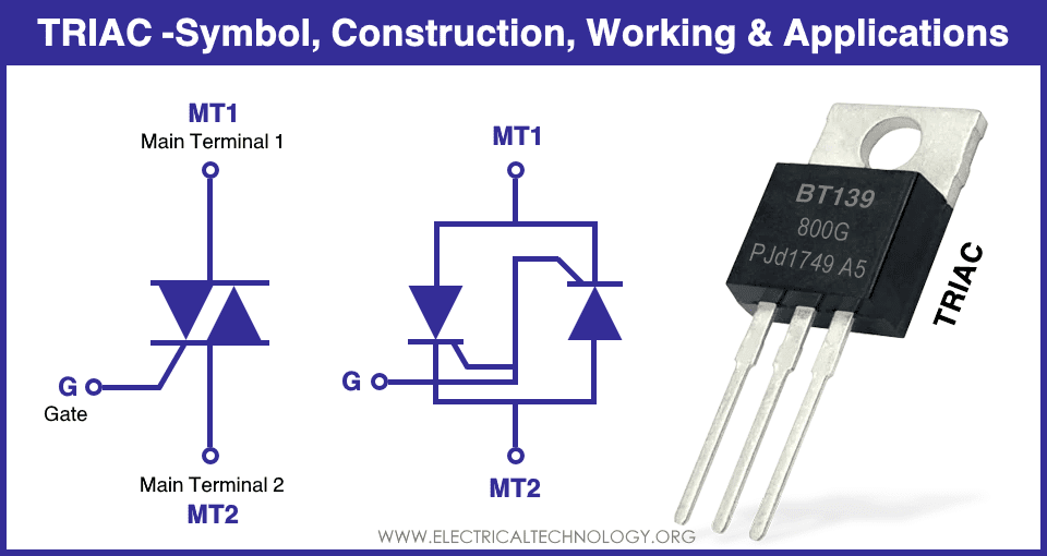
Symbol of TRIAC
The symbol of TRIAC represents two thyristors connected in antiparallel having a common gate. Its equivalent two-thyristor structure is also given for better understanding.

Just like thyristor, it has three terminals but their names are different except for Gate. It is due to the fact that each terminal is made by connecting the anode and cathode of SCR together. Therefore, both terminals are either called Anode or Main Terminal MT.
Construction of TRIAC
TRAIC is a four-layer device that is made from a combination of two antiparallel SCRs having three terminals Gate, MT1 and MT2.

Both main terminals (MT1 and MT2) electrodes are connected with both P and N regions of both SCRs. So that it can conduct current in both directions. The gate metallic electrode is also connected with both P and N regions. It allows the TRIAC to be triggered by both positive as well as negative gate currents.
TRIAC is a bidirectional switch, it can conduct in both directions but it is not symmetrical. Its asymmetrical structure is the reason TRAIC has asymmetrical switching.
- Related Post: What is the Difference Between DIAC and TRIAC?
Operation of TRAIC
The operation of TRAIC resembles thyristor. When the voltage is applied, it will not conduct unless the voltage does not exceed the break over voltage VBO or a gate pulse is applied.
As we know that TRAIC can conduct for both polarities of applied voltage and it can be triggered by both polarities of gate voltage for either direction. Therefore, the TRAIC can operate in 4 modes.
The following voltages are taken with respect to the MT2 terminal such as MT1 voltage with respect to MT2 and Gate voltage with respect to MT2.
Mode 1 : MT1= +ve, Gate= +ve
In this mode, the applied voltage at MT1 is positive with respect to MT2. By applying a positive gate pulse, the TRAIC will trigger into forward conduction and the current will flow from MT1 to MT2.
Mode 2 : MT1= +ve, Gate= -ve
In this mode, the applied voltage is the same i.e. MT1 is positive with respect to MT2. But the gate pulse is negative. Since the gate is connected with the N region of TRIAC, it will trigger it into forward conduction while the current direction will remain the same.
Mode 3 : MT1= -ve, Gate= +ve
In this mode, the applied voltage polarities are swapped i.e. MT1 is negative with respect to MT2. But the gate pulse is positive. The gate pulse will trigger TRAIC into reverse conduction from MT2 to MT1.
Mode 4 : MT1= -ve, Gate= -ve
In this mode, both the applied voltage and the gate voltage are negative. The negative gate pulse triggers the TRAIC into reverse conduction
Mode 1 and mode 2 represents an operation in the 1st quadrant where the current and voltage are positive while mode 3 and mode 4 represent operation in the 3rd quadrant where the voltage and current both are negative.
While the gate pulse can trigger TRAIC in either direction, it is best to use a positive gate pulse for operation in the 1st quadrant and negative gate pulse for operation in the 3rd quadrant due to their increased sensitivity. Mode 2 and 3 require more gate current that mode 1 and 4 to trigger TRIAC.
V-I Characteristic of TRIAC
The following characteristic curve shows the relationship between the applied voltage and the current flowing through the TRIAC. It operates in only the 1st and 3rd quadrants. Its operation is the same as SCR but it can also operate in the 3rd quadrant.

The current I increase when either voltage V exceeds the break over voltage VBO or if a gate pulse is applied. As soon as, the device switches into ON-state, the voltage reduces to ON-state voltage and the current exceeds. It will remain in ON-state until the current reduces below holding current IH.
TRAIC is the combination of two SCR in a single package, therefore, it also has the same electrical characteristics as individual SCR in each direction such as break down voltage, trigger voltage, holding current.
Advantages & Disadvantages of TRIAC
Advantages
The advantages of TRIAC are given below:
- It can conduct and regulate both halves of an AC waveform.
- It is compact and requires a smaller heat sink as opposed to using two SCR.
- It requires only one fuse for protection.
- Positive as well as negative gate pulse can be used to trigger TRAIC.
- It does not require a diode in parallel for reverse protection as in SCR.
Disadvantages
- Its switching is asymmetrical for both halves of AC.
- Asymmetrical switching creates harmonics in the system causing numerous problems.
- Its power rating is lower as compared to SCR.
- It is less reliable than SCR.
- It has a lower switching speed.
- Requires caution while triggering as it can be triggered in either direction.
- Its dv/dt rating is lower than SCR.
Applications of TRIAC
TRIAC is used for low to medium AC power regulation. Due to their asymmetrical switching, a DIAC is used in series to its gate terminal to provide symmetrical triggering. A combination of both DIAC and TRIAC in a single package is available which is known as QUADRAC.
They are used for controlling the speed of motors, fans and light dimmers as well as heat control applications.
Related Posts:
- What are Thyristor and SCR? Types, Working and Applications
- What is Rectifier? Types of Rectifiers and their Working Principle
- What is MOSFET? Working, Types, Operation, and Applications
- What is Diode? Construction & Working of PN Junction Diode
- What is BJT? Construction, Working, Types and Applications