Schematic Diagram of Digital Voltmeter & Continuity Circuit Tester With LCD Display Using STM8S003F3 Microcontroller with Firmware
You may have come across these simple and small digital voltmeters on the web and in automotive workshops, such as a digital circuit tester with an LED display used to measure DC voltage and check continuity. Some of them are modified versions, like a DC phase tester with voltage and polarity measurement.
Although most of them use the STM8S003F3 microcontroller, many Chinese brands use mixed and unknown ICs and microcontrollers. For example, the basic versions of digital voltmeters use the Holtek HT67F488/HT67F489, while others use the DSN-DVM-568 microcontrollers or blank ICs (without printing the Name or code on it).
The STM8S003F3 is an 8-bit microcontroller from STMicroelectronics that can be used to create a digital voltmeter. It includes 8KB of flash memory, 640 bytes of RAM, and 16 I/O pins.
Thanks to ba0sh1’s modifications to the circuit and programming code, the digital voltmeter implementation using the STM8S003F3 microcontroller has achieved improved accuracy and resolution compared to the basic circuit provided by the manufacturer.
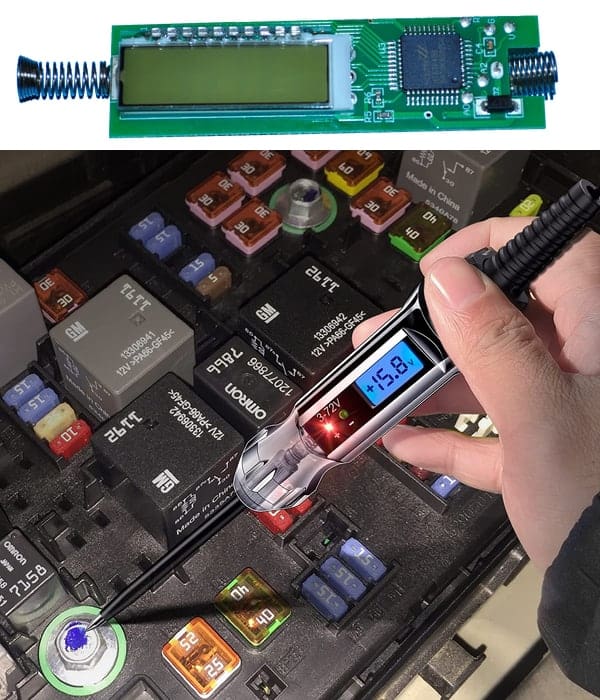
If you’re interested in a reliable and highly recommended tool like this one for routine checkups, maintenance, troubleshooting and testing electrical/electronic components, you can get one at the following link.
Get Digital LCD Circuit Tester
Related Posts:
- Circuit Diagram of Digital Voltmeter Using Using ICL7107
- Circuit Diagram of Digital Voltmeter Using 8051 Microcontroller
In this article, we will discuss the implementation details of modifying the digital voltmeter using the STM8S003F3 microcontroller additionally used as continuity and circuit tester, along with the project source code.
Components Required
To build a digital voltmeter using the STM8S003F3, we need the following components:
- STM8S003F3 Microcontroller
- Voltage Regulator ICs = LD1117A-33 and 7805
- Shunt Regulator IC = TL431LP
- 7-segment 4-digits LED display
- Diodes, Capacitors and Resistors
Circuit Diagram
Click image to enlarge
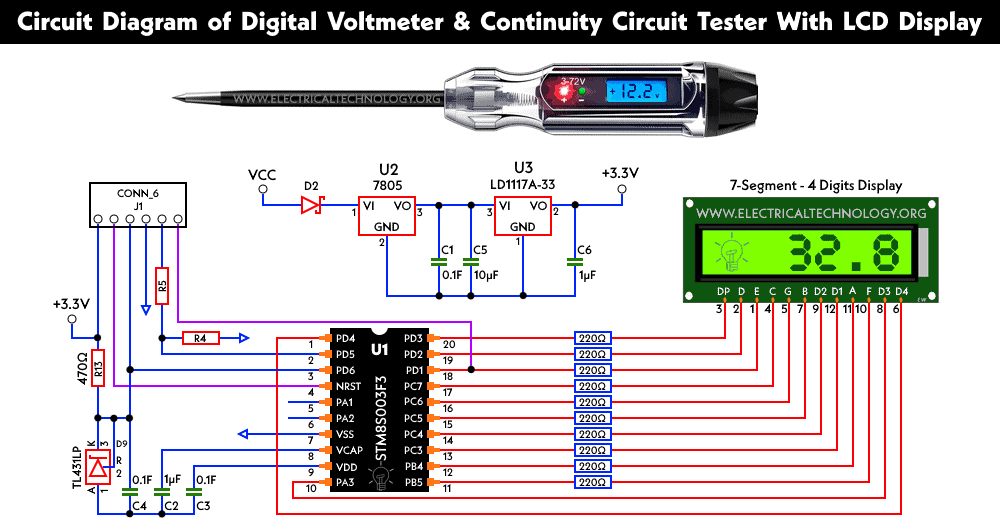
Overview of the Circuit:
The circuit for the digital voltmeter using the STM8S003F3 microcontroller consists of several components such as the STM8S003F3 microcontroller, LCD display, voltage divider network, and a few other passive components. The voltage divider network is used to reduce the voltage to a level that can be read by the microcontroller. Some of the main ICs and microcontrollers used in this project are as follow.
STM8S003F3P6
STM8S003F3P6 is a microcontroller chip from STMicroelectronics, which is a member of the STM8 family of 8-bit microcontrollers. The STM8S003F3P6 has a small form factor and is available in a 20-pin SOIC (Small Outline Integrated Circuit) package. It has a core frequency of up to 16 MHz and features 8KB of flash memory, 1KB of RAM, and 128 bytes of EEPROM memory. It also includes a number of built-in peripherals, including 1 16-bit timer, 1 8-bit timer, 1 USART (Universal Synchronous/Asynchronous Receiver/Transmitter), and 1 SPI (Serial Peripheral Interface) interface. The STM8S003F3P6 microcontroller is designed for use in a variety of applications, including industrial control, automotive, consumer electronics, and home automation.
LD1117A-33 and 7805
LD1117A-33 and 7805 are a voltage regulator ICs (integrated circuit) that provides a fixed output voltage of 3.3 volts and 5 volts respectively. They are low-dropout linear regulator that can handle input voltages up to 15 and 35 volts and can supply up to 800mA and 1 ampere of current. The 7805 and LD1117A-33 are commonly used in electronic circuits to regulate the voltage and provide a stable power supply to other components in the circuit. It is often found in applications such as battery-powered devices, embedded systems, and other low-power electronics.
TL431LP
TL431LP is a three-terminal adjustable precision shunt regulator IC (integrated circuit). It is a low-power device that provides a precise output voltage reference that can be adjusted using two external resistors. The TL431LP is designed to operate over a wide range of input voltage (up to 36 volts) and can provide an output voltage in the range of 2.5 volts to 36 volts. It has a low output noise and a low temperature coefficient, which makes it suitable for use in precision voltage regulation applications. The TL431LP is commonly used in a variety of applications such as power supplies, battery chargers, LED drivers, and other electronic circuits where precise voltage regulation is required.
A digital voltmeter is a device that is used to measure voltage levels in an electrical circuit. In this article, we will explore how to build a digital voltmeter using the STM8S003F3 microcontroller.
STM8S003F3 is an 8-bit microcontroller based on an advanced STM8 core, offering a high level of integration and low power consumption. It is widely used in embedded systems for its excellent performance and low cost.
Working of the Circuit:
The voltage divider circuit is used to step down the input voltage to a safe level, which can be measured by the ADC. The ADC is used to convert the analog voltage signal into a digital signal, which can be displayed on the 7-segment LED display. The capacitors and resistors are used to stabilize and filter the signal.
The ADC (analog-to-digital converter) converts the analog voltage signal into a digital signal by comparing the input voltage with a reference voltage. The resolution of the ADC depends on the number of bits used in the converter. For example, an 8-bit ADC can measure a voltage range of 0-5V with a resolution of 19.53 mV per step.
The software for the digital voltmeter is written in C language using an Integrated Development Environment (IDE). The software reads the voltage signal from the ADC, converts it into a digital value, and displays it on the 7-segment LED display. The software can also be programmed to implement additional features, such as peak voltage measurement, voltage averaging, and voltage logging.
To summarize, a digital voltmeter using the STM8S003F3 is a simple and cost-effective solution for measuring voltage signals in various applications. It requires a voltage divider circuit, an ADC, a 7-segment LED display, and the STM8S003F3 microcontroller. The software can be programmed to implement additional features, and the output can be interfaced with other devices for further analysis and processing.
Firmware Source Code
The firmware can be downloaded which is listed on GitHub repository from the original author ba0sh1.
Notes from the Firmware’s Author:
- The code used in this project is compiled with “IAR Embedded Workbench for STMicroelectronics STM8”. The “KickStarter” edition is free but has an 8K code size limit, which is sufficient for STM8S003F3.
- Although the library is written in C, it is not as efficient as assembly code. Even with full 16Mhz clock and optimal settings, the maximum achievable I2C clock is 63KHz, but 50KHz is used for testing purposes.
- Although the COSMIC compiler was attempted, its efficiency was found to be worse.
- In the Arduino environment, you can change the I2C clock by modifying the TWI_FREQ variable in <arduino>librariesWireutilitytwi.h, or by following Nick Gammon’s article.
- Unfortunately, STM8s does not support per-pin interrupt configuration, which makes simulating the interrupt mode costly in terms of CPU time and directly responsible for the slow I2C clock support. Therefore, if it is possible to change the MCU, it would be better to use the hardware I2C directly.
- The LED display is write-only, and I2C reading is not implemented.
- Adafruit’s LED backpack uses Holtek HT16K33. Although all HT16K33 display modes are emulated, keyboard scan functions are not. However, Adafruit’s LED backpack does not have a keyboard interface either.
- The average current consumption is about 2.6mA at 3.3V, which is higher than HT16K33’s 1-2mA.
- To develop and debug this library, Bus Pirate’s 2Wire mode is required. Using 2Wire mode, each bit can be clocked individually to trace the I2C state.
- Apart from being cheaper, there is nothing better than Adafruit’s LED backpack. The project was done simply because it was possible.
- To modify the hardware, only the MCU, two resistor networks, and some bypass capacitors are required.
Advantages
1. The digital voltmeter is more accurate and precise than analog voltmeters.
2. The STM8S003F3 microcontroller is low cost and readily available in the market.
3. The microcontroller can be programmed to perform other tasks besides measuring voltage.
4. The digital display is easy to read and interpret.
5. The circuit is simple and inexpensive to build.
6. The voltmeter can be powered using batteries, making it portable and easy to use in the field.
Want One LCD Circuit Tester with Voltmeter and Continuity Tester for General and Automotive Applications? Get One below
Get Digital LCD Circuit Tester
Related Posts:
- USB Propeller LED Fan Clock – Circuit Diagram & Project Code
- Circuit Diagram of Cable and Wire Tester Circuit Diagram
- How to Test a Capacitor by Digital & Analog Multimeter – 6 Methods
- How to Test a Relay? Checking SSR & Coil Relays
- How to Test a Diode using Digital & Analog Multimeter – 4 Ways.
- How to Test & Fix the Printed Circuit Board (PCB) Defects?
- How to Test a Transistor using Multimeter – NPN & PNP – 4 Ways
- How to test a battery with Test meter?
- How to find The value of Burnt Resistor ( By three handy Methods )
- How To Locate Faults In Cables? Cable Faults, Types & Causes
- Smart Home Automation System – Circuit and Source Code
- Soldering Iron Temperature Controller
- Automatic LED Emergency Light Circuit
- Automatic Night Lamp Using Arduino
- Automatic Bathroom Light Switch Circuit Diagram and Operation
-
 How to Install a Wireless Smart Scene Switch
-
 How to Wire Smart Scene Controller Switch
-
 How to Install a Home and Away Wireless Smart Switch
-
 How to Install a Wire-Free Smart Dimmer Anywhere Companion
-
 How to Wire a Smart Wireless Switch and Anywhere Companion
-
 Wiring a Smart Dimmer Switch Companion with a Digital Dimmer