Wiring Installation of 40A & 50A Spa Panel for Hot Tub using 2-Pole Breaker and GFCI
A spa panel is a small, outdoor-rated disconnect enclosure that contains a 2-pole GFCI breaker and serves as the required maintenance or emergency disconnect for a 240V hot tub. The most common configuration is single-phase 120/240V, consisting of L1 Hot 1, L2 Hot 2, Neutral, and Ground. When the hot tub is located more than 5 ft 1.5 m from the main panel, a spa panel must be installed as the disconnecting means within sight of the equipment, in accordance with NEC 680.13.
The spa electrical enclosure or junction box is wired in the same manner as a subpanel. The neutral and grounding busbars are kept separate and are not bonded, unlike in the service disconnect where bonding of both ground and neutral is required.
Before beginning the wiring installation, see the NEC requirements for spas, hot tubs, and electrically heated pools provided immediately after the wiring tutorials in this article.
In the following wiring tutorial, the installation of 40A and 50A – 240V rated GFCI breakers and overcurrent protection devices for a hot tub installed in a spa panel is shown in the following figures.
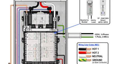
Wiring 50A – 120/240V Spa Panel using 2-P GFCI & Breaker
If the hot tub is located faraway than the the main panel, a disconnecting means (not less than 1.5m (5 ft) from the inside wall of the spa or hot-tub) is required within sight of the equipment. For this purpose, a rainproof, outdoor-rated NEMA 3R spa panel is installed. The spa panel contains a 2-pole, 240V GFCI breaker connected to two hot buses, along with separate neutral and grounding busbars. The neutral and ground are isolated and not electrically bonded, as this enclosure functions as a subpanel.
As shown in the wiring diagram for 50A dedicated GFCI panel, a 2-pole, 50A/240V standard breaker is installed in the main panel and connected to the Hot 1 and Hot 2 busbars. This breaker provides overcurrent protection for the feeder conductors supplying the spa panel.
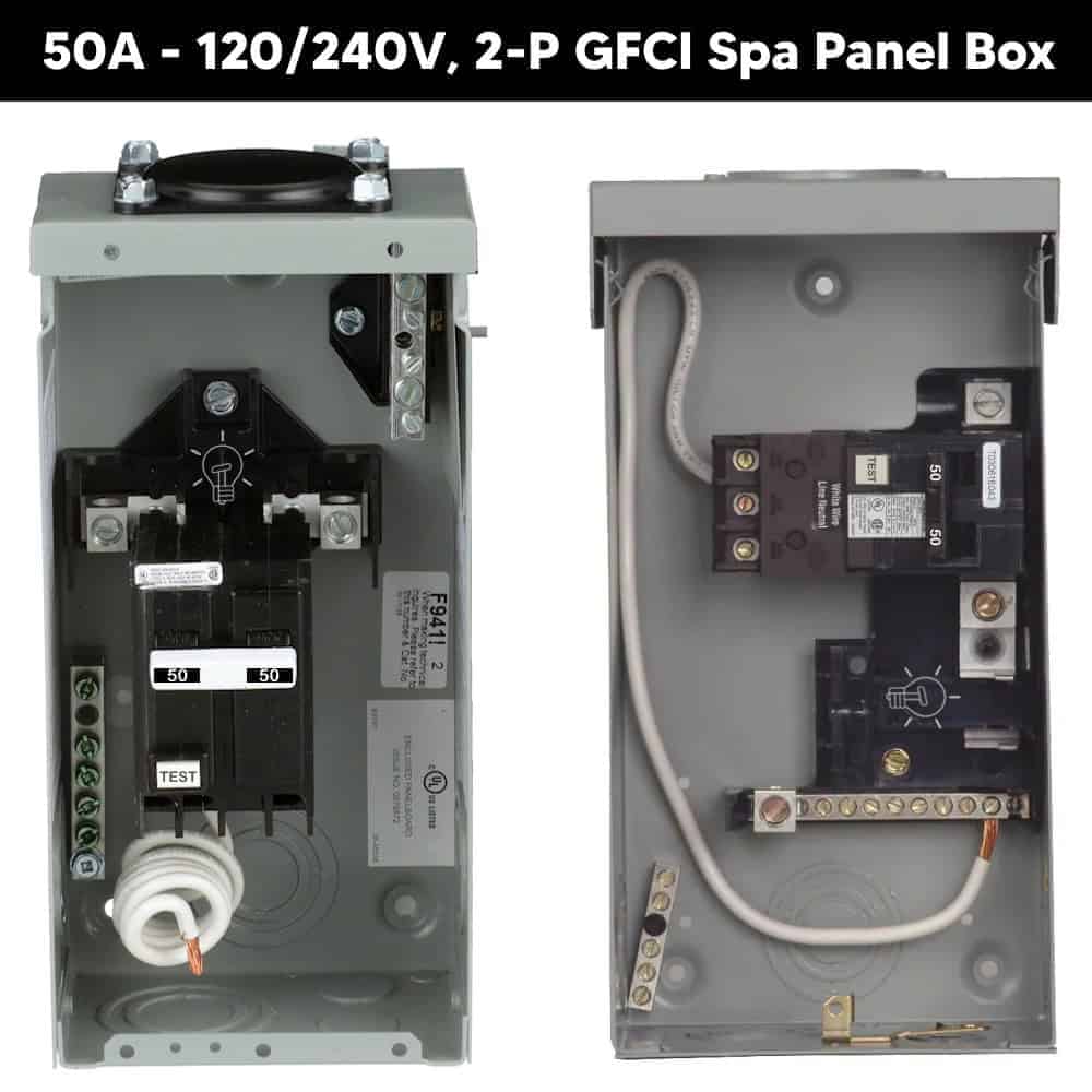
Inside the spa panel, a 2-pole, 50A, 120/240V GFCI breaker is snapped onto the two hot bus slots. The neutral conductor and the equipment grounding conductor (EGC) are run from the main panel to the spa panel and terminated on their respective isolated busbars.
From the spa panel, four conductors (2 Hots, 1 Neutral, and 1 Ground) are connected to the spa control box and terminated as Hot 1, Hot 2, Neutral, and Ground.
Click image or open in a new tab to enlarge
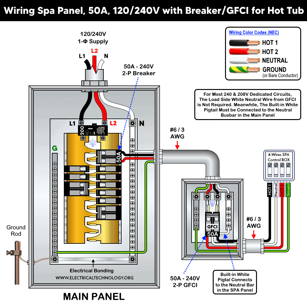
For this 50A circuit, the appropriate conductor size is #6 AWG copper, as per NEC Table 310.16. The equipment grounding conductor (EGC) may be #10 AWG copper for a general 50A circuit, as specified in NEC Table 250.122. However, the equipment bonding conductor for pools and spas must be #8 AWG insulated solid copper or larger to reduce voltage gradients with in 5 ft of pool area, as per NEC 680.26, in accordance with NEC 250.8.
Good to Know:
- A 240V hot tub must be hardwired to a dedicated circuit with a GFCI (Ground Fault Circuit Interrupter) safety disconnect.
- In the spa panel the GFCI is wired downstream the standard breaker. The standard 2-pole 50A – 240V breaker can be used as maintenance disconnect, while the 2-pole 50A – 240V GFCI breaker can be used as emergency disconnect.
- For most 240V & 208V dedicated circuits, the load side white neutral from GFCI is not required. Meanwhile, the built-in white pigtail must be connected to the neutral busbar in the main panel.
- In a spa panel, neutral and ground must be isolated. Remove any bonding screw or strap if present.
- Connect the GFCI breaker neutral pigtail to the spa panel neutral bar
- The spa neutral must terminate on the GFCI breaker’s load side neutral terminal, not on the neutral bus. If landed on the neutral bus, the breaker will trip instantly.
Wiring 40A – 120/240V, 2-Pole GFCI Breaker for Hot Tub
If the hot tub or spa is located close to the main panel (not less than 5 ft (1.5m)), it is permitted to install a 2-pole GFCI breaker in the main panel and use it as the disconnecting means, without installing an additional spa panel. In simple terms, a single 2-pole GFCI breaker in the main panel is sufficient, instead of using a standard 2-pole breaker along with a separate 2-pole GFCI in a spa subpanel.
The following wiring diagram shows a hot tub, whirlpool spa, electric water heater, pool, or fountain supplied and protected by a 2-pole GFCI circuit breaker using a three-wire system consisting of two hot conductors, one neutral, and one equipment grounding conductor.
In this 2-pole, 3-wire GFCI wiring arrangement, the built-in white pigtail from the GFCI breaker is connected to the neutral busbar in the main panel. The two line conductors, Hot 1 and Hot 2, from the main panel L1 and L2 busbars of a single-phase 240V system are connected to the GFCI breaker input terminals as the breaker snaps onto the L1 and L2 busbar slots in the load center.
As shown in the diagram, the three load terminals of the GFCI breaker are connected to the spa control box according to the printed terminal markings. The center terminal is the neutral, while the first and last terminals are the two hot conductors, Hot 1 and Hot 2. Finally, the equipment grounding conductor from the ground busbar is connected to the grounding terminal in the spa control box.
Click image or open in a new tab to enlarge
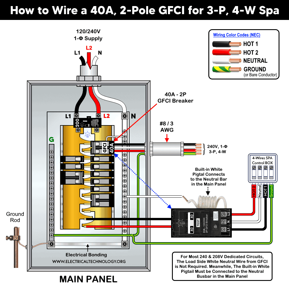
The right wire size for 40A circuit is #8 AWG copper, as per NEC Table 310.16. Similarly for the above circuit, the equipment bonding conductor for pools and spas must be 8 AWG or larger solid insulated copper in accordance with NEC 680.26 and 250.8.
NEC Requirements for Spa Panel & Hot Tub
- All hot tubs, spas, swimming pools, wading pools, therapeutic pools, decorative pools, fountains, and hydromassage bathtubs must be protected by a Class A GFCI or a special-purpose ground-fault circuit interrupter (SPGFCI), as per NEC 680.44(A) in accordance with NEC 680.5.
- Feeders and branch circuits installed in wet locations must include an equipment grounding conductor and be electrically bonded using insulated copper conductors sized in accordance with NEC Table 250.122. The grounding conductor shall not be smaller than 12 AWG. The same requirements apply to flexible cords, plugs, and terminals used for spas and bathtubs, as specified in NEC 680.7 and 680.8.
- Flexible cords used for permanently installed hot tubs shall not exceed 3 ft (900 mm) in length, as required by NEC 680.8(A).
- The ampacity of branch-circuit conductors and the rating of overcurrent protective devices OCPDs shall be not less than 125 percent of the total nameplate-rated load for electric water heaters and swimming pool heat pump equipment, in accordance with NEC 680.10.
- At least one 15A or 20A, 120V, GFCI-protected receptacle supplied from a general-purpose branch circuit must be installed within the equipment area, as required by NEC 680.12(B). All receptacles supplying power to a hot tub or spa must be GFCI protected, in accordance with NEC 680.44.
- One or more disconnecting means must be provided within sight of the equipment and located not less than 5 ft (1.5) m away. The disconnect must be readily accessible and capable of disconnecting all ungrounded conductors supplying pool, spa, fountain, or hot tub equipment, except for lighting, as required by NEC 680.13.
- In corrosive or wet environments, approved wiring methods include intermediate metal conduit, rigid metal conduit, reinforced thermosetting resin conduit, rigid polyvinyl chloride PVC conduit, or liquid tight flexible nonmetallic conduit LFNC. Aluminum conduit or tubing is not permitted for these installations, in accordance with NEC 680.14.
- Junction boxes and electrical enclosures used for GFCI connections must be listed, labeled, and identified as swimming pool junction boxes, in accordance with NEC 680.24(A)(1) and 680.24(B)(2), and must meet the following spacing requirements:
- Vertical spacing: The enclosure shall be installed not less than 4 in (100 mm) above finished ground level or the pool deck, measured from the bottom of the box. When measured above the pool water level, it shall be installed not less than 8 in (200 mm) above the maximum water level.
- Horizontal spacing: The enclosure shall be installed not less than 4 ft (1.2 m) from the inside wall of the pool.
- Equipotential bonding using a solid copper conductor not smaller than 8 AWG is required to reduce voltage gradients in the pool and spa area, in accordance with NEC 680.26 and NEC 250.8.
- All receptacles rated for 125/250V, 60A or less, and located within 10 (ft 3) m of a pool, spa, or hot tub must be GFCI protected. Receptacles supplying power directly to spa or hot tub equipment must also be GFCI protected, as required by NEC 680.43(2), 680.43(3), and 680.44(A).
Precautions:
- Disconnect the power source and verify that it is completely switched OFF before servicing, repairing, or installing any electrical equipment. To do this, turn OFF the main switch in the main panel.
- Never stand on or touch wet surfaces, and avoid contact with metal parts while performing installation or repair work.
- Carefully read all cautions and instructions, and follow them strictly while performing this tutorial or any other practical electrical work. Never attempt to experiment with electricity without proper guidance and safety precautions, as it is dangerous and can be fatal. Always carry out installation and repair work in the presence of experienced and qualified personnel who have the knowledge and practical skills to handle electrical systems safely.
- Performing electrical work on your own can be dangerous and, in some cases, illegal. Consult a licensed electrician or the electric power supply provider before making any changes or modifications to electrical wiring or connections.
- The author shall not be held liable for any losses, injuries, or damages resulting from the use or misuse of this information, or from attempting any circuit in an incorrect manner. Exercise extreme caution at all times. Electricity is inherently dangerous and must be handled with the highest level of care.
Resources:
Standard Breakers & GFCI Breakers Wiring Installations
- How to Wire a 1-Pole GFCI
- How to Wire a 2-Pole GFCI
- How to Wire a 3-Phase, 3-Pole GFCI
- How to Wire a 1-Pole Breaker
- How to Wire a 2-Pole Breaker
- How to Wire a 3-Pole Breaker
- How to Wire a Tandem Breaker
- How to Wire GFCI Circuit Breakers
- How to Wire an AFCI Breaker
Sizing Breakers, Wires, and Panels
- How to Size a Circuit Breaker?
- How to Size a Breaker and Wires in AWG with EGC for Load?
- How to Find the Proper Size of Wire & Cable In Metric & Imperial Systems
- How to Size a Load Center, Panelboards and Distribution Board?
- How to Determine the Right Size Capacity of a Subpanel?
- How to Find the Right Wire Size for 100A Service 120V/240V Panel?
- How to Size Service-Entrance Conductors and Feeder Cables?
- How to Size Feeder Conductors with Overcurrent Protection
- How to Size a Branch Circuit Conductors with Protection?
- How to Size Equipment Grounding Conductor (EGC)?
- How to Size Grounding Electrode Conductor (GEC)?
- How to Size Motors FLC, HP, Voltage, Breaker Size and Wire Size
- What is the Correct Wire Size for 100A Breaker and Load?
- What is the Right Wire Size for 15A Breaker and Outlet?
- What is the Suitable Wire Size for 20A Breaker and Outlet?
General Outlets and GFCI/AFCI Receptacles Wiring
- How to Wire an Outlet Receptacle? Socket Outlet Wiring Diagrams
- How to wire a GFCI Outlet?
- How to Wire GFCI Combo Switch and Outlet
- How to Wire an AFCI Combo Switch
- How to Wire an AFCI Outlet?
- How to a Wire 3-Way Combination Switch and Grounded Outlet?
- How to Wire Combo Switch and Outlet? – Switch/Outlet Combo Wiring Diagrams
- How to Wire a 15A – 120V Outlet – NEMA 5-15 Receptacle
- How to Wire a 20A – 120V Outlet – NEMA 5-20 Receptacle
- How to Wire a 15A – 240V Outlet – NEMA 6-15 Receptacle
- How to Wire a 20A – 240V Outlet – NEMA 6-20 Receptacle
- How to Wire a 50A – 125/250V Outlet – NEMA 14-50 Receptacle
Switches Wiring
- How to Wire Single Pole, Single Throw (SPST) as 2-Way Switch?
- How to Wire Single Pole, Double Throw (SPDT) as 3-Way Switch?
- How to Wire Double Pole, Single Throw Switch? Wiring DPST
- How to Wire Double Pole, Double Throw Switch? Wiring DPDT
- How to Wire Double Switch? 2-Gang, 1-Way Switch – IEC & NEC
- How to Wire 4-Way Switch (NEC) or Intermediate Switch as 3-Way (IEC)?
- How to Wire Auto & Manual Changeover & Transfer Switch – (1 & 3 Phase)
Finding the Number of Breakers/Outlets in a Circuit
- How to Determine the Number of Circuit Breakers in a Panelboard?
- How to Find the Number of Outlets on a Single Circuit Breaker?
- How to Find Voltage & Ampere Rating of Switch, Plug, Outlet & Receptacle
- How to Calculate the Number of Fluorescent Lamps in a Final Sub Circuit?
- How to Calculate the Number of Incandescent Lamps in a Final Sub Circuit?
- How to Determine the Number of Lighting Branch Circuits?
- How to Determine the Number of Branch Circuits? – 3 Ways
- How to Find the Number of Lights on a Single Circuit Breaker?
Main Panels Wiring Tutorials
- How to Wire 120V/240V Main Panel? Breaker Box Installation
- How to Wire 208V/120V, 1-Phase & 3-Phase Main Panel?
- How to Wire 240V, 208V & 120V, 1 & 3-Phase, High Leg Delta Main Panel?
- How to Wire 277V/480V, 1-Phase & 3-Phase Main Service Panel?
- How to Wire a Subpanel? Main Lug Installation for 120V/240V
- Single Phase Electrical Wiring Installation in Home according to NEC & IEC
- Three Phase Electrical Wiring Installation in Home – NEC & IEC
- How To Wire a Single Phase kWh Meter – 120V/240V
- How to Wire a Three-Phase Meter? 120/208/240/277/347/480/600V
General Wiring Installation Tutorials:
- How to Toggle Electric Water Heater Between 120V and 240V?
- How to Wire 120V Water Heater Thermostat – Non-Simultaneous?
- How to Wire 240V Water Heater Thermostat – Non-Continuous?
- How to Wire 3-Phase Simultaneous Water Heater Thermostat?
- How to Wire Twin Timer for 120V/240V Circuits – ON/OFF Delay
- How to Wire ST01 Timer with Relay & Contactor for 120V/240V Motors?
- How to Wire Multifunction ON/OFF Delay Timer for 120V/240V Motors?
- Even More Residential Wiring Installation Tutorials
Related Posts:
- Difference Between Circuit Breaker and GFCI
- Difference Between 1-Pole and 2-Pole Breakers – NEC & IEC
- Should GFCI Protection Be in the Main Panel or Receptacle?
- How Does a Standard Breaker Respond to Electrical Fault?
- Why Doesn’t a Standard Breaker Protract Against Ground Faults?
- How Do GFCI and Standard Breakers Respond to Ground Faults?
- Can you use 15A Breaker on 20A Circuit and Vice Versa?
- Can I Use a 1-Phase Breaker on a 3-Phase Supply & Vice Versa?
- Can I Use a 240V Breaker on a 120V Circuit and Vice Versa?
- Can You use a 15A Outlet on a 20A Circuit and Vice Versa?
-
 What Happens When You Press TEST and RESET on a GFCI
-
 Wiring Z-Wave Smart Switch, Dimmer & Fan Speed Controller
-
 How to Wire a Smart Switch in a 120/240V Load Center
-
 How to Wire 15A and 20A Wi-Fi Smart GFCI Outlets
-
 How to Wire a 15A Wi-Fi Smart Outlet in a Smart Panel
-
 How to Wire Smart AFCI/GFCI Breaker in a Smart Load Center