Dahlander Motor: Speed Control using Dahlander Connection
How to Use Dahlander Connection to Control the Speed of a Pole Changing Motor?
As we know, the speed control of an induction motor is little bit complex as compared to speed control of DC Motors. The speed of AC motors can only be adjusted by changing the number of poles or power supply’s frequency.
N = 120f ÷ P
Where:
- N = Speed of Motor
- f = Frequency of power supply
- P = Number of poles
A Dahlander motor control circuit is nothing special, but a special motor with an additional windings designed for speed control in induction motors, as compared to the VFD (variable frequency drives) which regulate the motor’s speed by adjusting its frequency.
In simple words, we changes the number of poles instead of frequency in Dahlander motor control circuits.
In this article, we will show how to use the Dahlander connections to control the speed of motor and it rotation of direction with the help of power, wiring and control circuit diagrams?
What is a Dahlander Motor?
The Dahlander motor (named after a Swedish engineer – Robert Dahlander – 1897), also known as the “two-speed or multi-speed motor,” is a type of three-phase induction motor that stands out due to its dual-speed capabilities. This is achieved through a distinctive winding configuration for changing the poles of the motor that enables the motor to function at two or multiple speeds.
It has an additional winding (with a total of 6-terminals) which is used as a pole changing feature to control the speed and direction of rotation of the motor.

Construction
Unlike conventional induction motors, the Dahlander motor features two sets of windings per phase, resulting in a total of six terminals. These windings can be interconnected in different ways to facilitate two-speed operation. The basic premise involves tapping into different parts of the windings to alter the effective number of poles and thereby control the motor’s speed.
Working Principle
When the motor operates in high-speed mode, a connection is established that effectively doubles the number of poles, resulting in a lower synchronous speed. Conversely, in low-speed mode, the windings are connected differently to maintain the standard number of poles, thus running at a higher synchronous speed. These configurations allow the Dahlander motor to switch between its two speeds without the need for complex external control systems.
What is the Dahlander Connection?
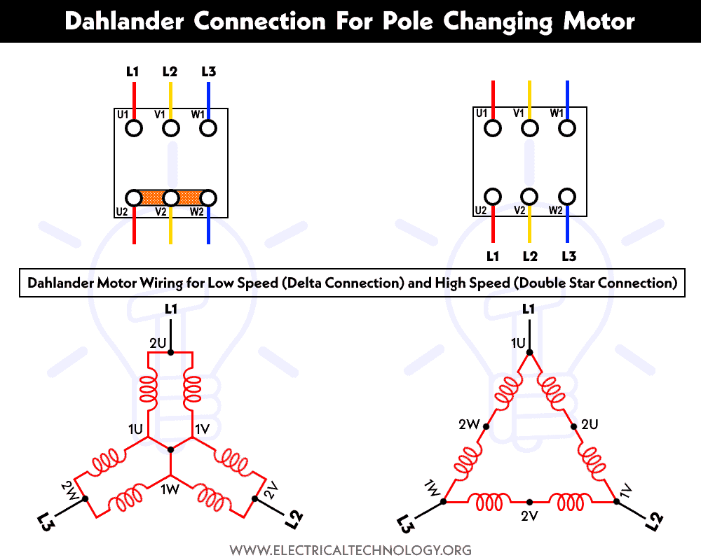
The Dahlander connection, also known as the “Dahlander winding and two-speed motor connection,” is a specialized configuration used in electric motors to provide two different speeds. It achieves this by connecting the motor windings in a specific manner, allowing the motor to operate at either a higher or lower speed based on the configuration. These connections are primarily used in three-phase induction motors for motor windings as follow:
- Star (Y) /Star (Y) and Star (Y)
- Star (Y) and Star (Y) / Delta (Δ)
- Delta (Δ) /Star (Y) and Star (Y)
Dahlander connection and control circuit is used in dual / tap changed motors having a separate winding. It has a set of windings per phase (e.g. two coils per pole). This way, we get total six number of terminals instead of three. These terminals can be configured for various speeds and to change the rotational direction of three-phase motors.
Operation of the Circuit
The Dahlander connection works by utilizing the inherent characteristics of the motor windings. A three-phase motor has multiple windings that produce magnetic fields with different numbers of poles. The Dahlander connection exploits this feature by tapping into different points along the winding to create different configurations. By doing so, the motor can effectively switch between two-speed settings.
The primary principle underlying the Dahlander connection is the change in the number of poles in the motor. When the connection is switched from one configuration to another, the effective number of poles changes, leading to a change in the motor’s synchronous speed. This alteration in speed is what allows the motor to operate at two different speeds.
Now, let’s see how to use the Dahlander connections and control circuits for different speed control of 3-phase induction motors.
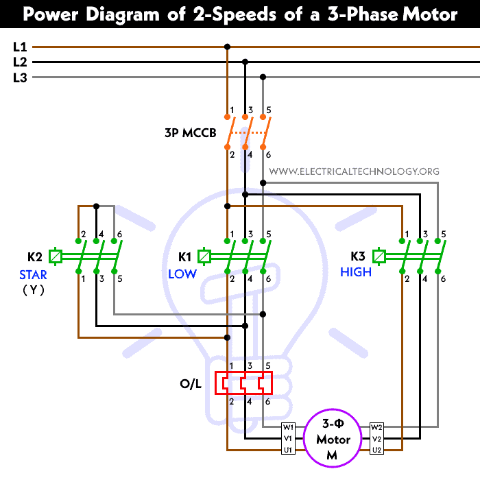
Power & Control Diagrams
Note: We have only added the power diagrams, you may see the control circuit diagrams with working and operation for each post published before. (links are given for each article at the bottom of each power diagram).
2-Speed, 1-Direction
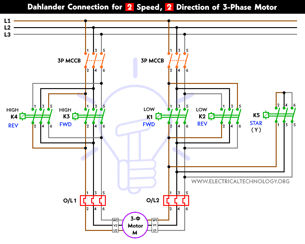
2-Speed, 2-Directions
3-Speed, 1 Direction (Multispeed Control)

Applications of Dahlander Connection
- Crane Systems: Dahlander-connected motors find application in crane systems where the motor needs to operate at both low speeds for precise positioning and higher speeds for material movement.
- Conveyor Belts: In industries involving material handling, such as mining and manufacturing, Dahlander-connected motors can be used to drive conveyor belts at varying speeds depending on the workload.
- Fans and Blowers: Ventilation systems often require variable speeds for different levels of air circulation. Dahlander connections offer a solution to achieve these speed variations.
- Machine Tools: Machine tools often need different speed ranges for cutting, shaping, and finishing operations. Dahlander-connected motors can cater to these requirements effectively.
Advantages
- Cost-Effective: Dahlander connections provide two-speed capabilities without the need for external speed control devices, making them cost-effective solutions.
- Simplicity: The design of Dahlander-connected motors is relatively straightforward, resulting in ease of maintenance and repair.
- Efficiency: These motors maintain their efficiency at both speed settings, ensuring optimal performance across the operational range without extra power loss like in VFDs.
Considerations
- Torque: It’s important to note that the torque produced by the motor may vary at different speeds. The torque-speed characteristics should be evaluated based on the application’s requirements.
- Switching: Switching between speed configurations might involve mechanical or electrical changes. Care should be taken to ensure smooth transitions and avoid wear and tear on components.
Related Posts:
- Star-Delta (Y-Δ) 3-phase Motor Starting Method by Automatic star-delta starter with Timer.
- Three Phase Motor Connection STAR/DELTA Without Timer – Power & Control Diagrams
- Three Phase Motor Connection Star/Delta (Y-Δ) Reverse / Forward with – Timer Power & Control Diagram
- Starting & Stopping of 3-Phase Motor from more than One Place Power & Control diagrams
- Control 3-Phase Motor from more than Two buttons – Power & Control Diagrams
- ON / OFF Three-Phase Motor Connection Power & Control Schematic and Wiring Diagrams
- Three Phase Motor Connection Reverse and Forward – Power and Control wiring diagrams
- Three Phase Slip Ring Rotor Starter – Control & Power Diagrams
- Even Motor Power & Control Circuit Diagrams for 3-Phase Motor


Thanks for posting this article, I found it helpful in understanding this type of motor. As I believe the motor has less poles in high speed, causing a higher synchronous speed, and faster rotation. Also, please note that the titles are listed in reverse for the diagram showing the delta and double wye configuration. But overall this article has been a big help, thanks.